1PosSSI/Analog
6.2 Brief Instructions on Commissioning the 1PosSSI/Analog
ET 200S Positioning
Operating Instructions, 05/2007, A5E00124871-04
243
Installation, Wiring, and Fitting
Install and wire the TM-E30S44-01 terminal module. Insert the 1PosSSI/Analog in the
terminal module (you can find detailed instructions in the
Distributed I/O Device
manual).
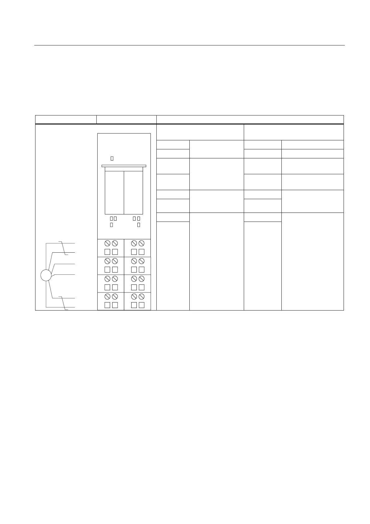
Table 6-1 Terminal assignment of the 1PosSSI/Analog
Terminal assignment View Remarks
Connection of the SSI Encoder:
Terminals 1-8
Connection of the Switches and the
Drive: Terminals 9-16
1: D 9: IN0 Minus limit switch
5: /D
Data from the SSI
encoder
13: IN1 Plus limit switch
3: B 14: IN2 Reducing cam; latch
signal
7: /B
Unused terminals
10: 24 VDC Encoder supply for the
switches
2: 24 V DC 12: QV+
6: M
Power supply for
SSI encoder
16: M
ana
Analog output ± 10 or
0 V to 10 V to connect
the drive
4: C 11: OUT
6)
326
(6'.$%
326
83 '1
66,
&
&
'
'
/
0
66,$QDORJ
8:/C
SSI clock (clock
line)
15: M
Digital output for direct
control or as a
directional signal for
the drive

 Loading...


