1PosUniversal/Digital
7.3 Terminal Assignment Diagram
ET 200S Positioning
Operating Instructions, 05/2007, A5E00124871-04
315
7.3 Terminal Assignment Diagram
Wiring Rules
If a position encoder with 5 V differential signals is used, the wires to the terminals 9 and 13,
the terminals 12 and 16, as well as at incremental encoders the wires to the terminals 11 and
15 have to be in twisted pairs and shielded.
If an incremental encoder with 24 V signal is used, the wires to the terminals 9, 11 and 12
have to be shielded.
The shield must be supported at both ends. You use the shield contact element (Order
Number: 6ES7 390-5AA00-0AA0) as a shield support.
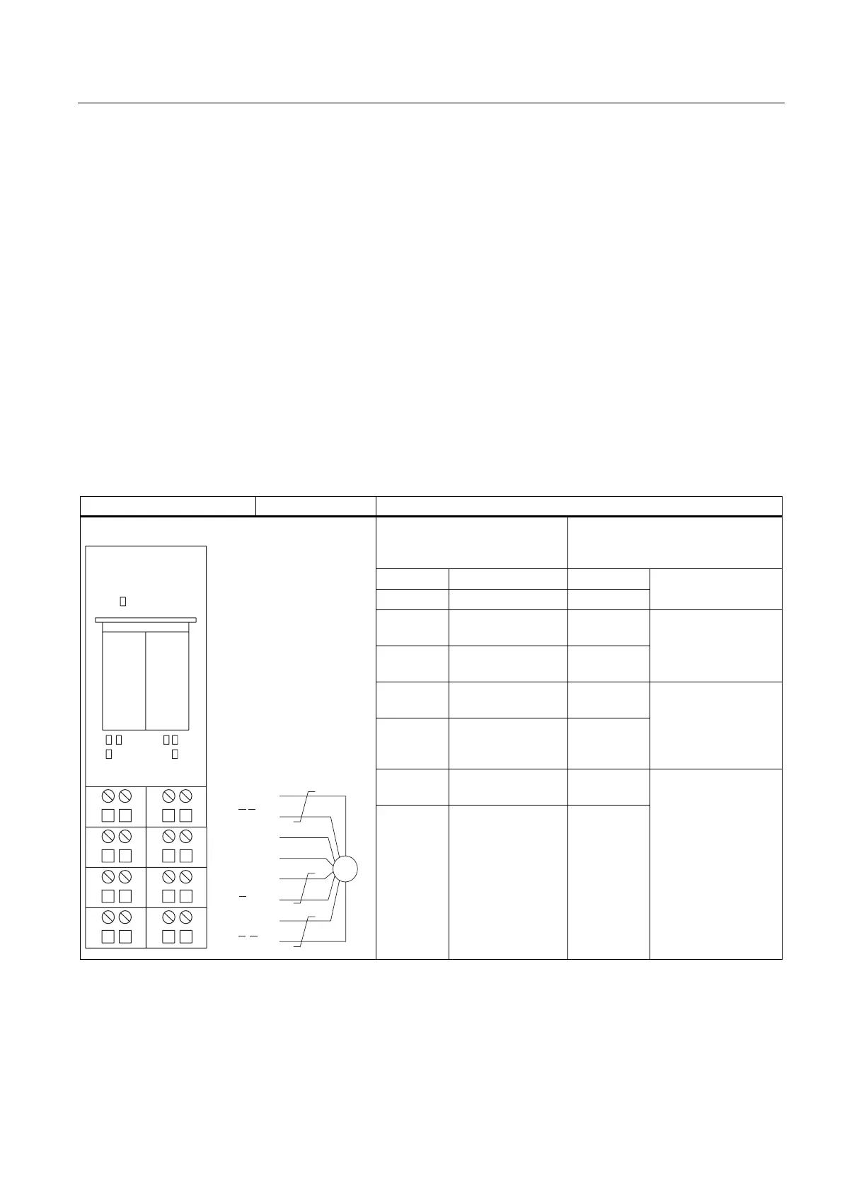
Terminal Assignment
The following table shows you the terminal assignment for the 1PosU:
Table 7-2 Terminal Assignment of the 1PosU
Terminal Assignment View Remarks
Connection of the Switches and
the Drive: Terminals 1-8
Connection of the Position Encoder
with 5 V Differential Signals or 24 V
Signals: Terminals 9-16
1: IN0 Minus limit switch 9: A / D
5: IN1 Limit switch plus 13: /A / /D
Track A / Data from
the SSI encoder
2: IN2 Reducing cam;
latch signal
10: 24 V DC
6: 24 V DC Supply for the
switches
14: M
Power supply for the
position encoder
3: OUT0 Travel minus or
rapid feed
11: B
7: 2L+ Load voltage
infeed for OUT0,
OUT1 and OUT2
15: /B
Track B
4: OUT1 Travel plus or
creep feed
12: N / C
6)
3268QLYHUVDO
(6'/$%
83 '1
326
(QF
$'
$'
%
%
1&
1&
'&9
0
'LJLWDO
8: OUT2 Rapid/creep feed
and travel
plus/minus
16: /N / /C
Track N / SSI clock
(clock line)

 Loading...


