Starting Up the PLC
11.4 PLC programming
11-173
SINUMERIK 802D sl Instruction Manual (BA), 05/2005 Edition
6FC5 397-0CP10-1BA0
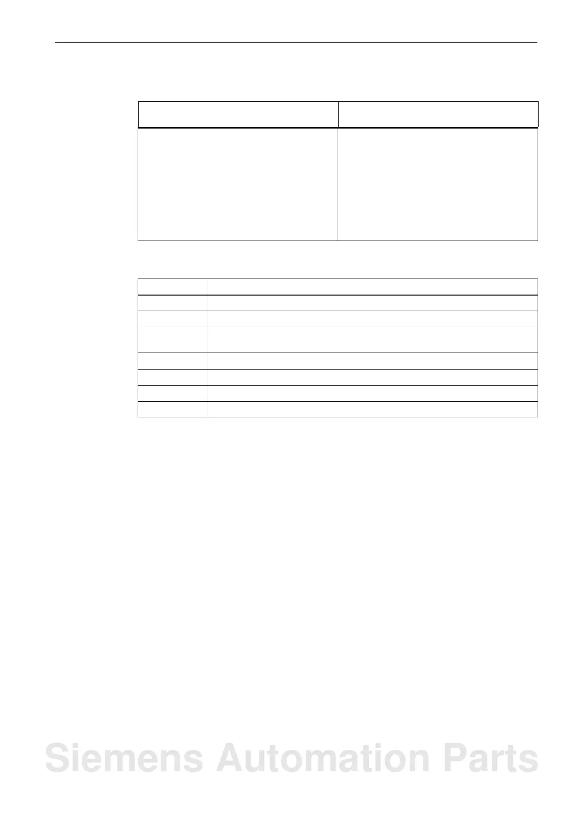
Table 11-5 802D Operand Ranges, continued
Access Method Valid Operand Ranges for
Programming 802D
Double Word Access VD(1000 0000–7999 9994)
ID(0–14)
QD(0–8)
MD(0–380)
AC(0–3)
–
–
AC(0–3)
KD (Constant)
Table 11-6 Special bit memory SM Bit Definition
SM bits
Description
SM 0.0 Bit memory with defined ONE signal
SM 0.1 Initial position: first PLC cycle ‘1’, subsequent cycles ‘0’
SM 0.2 Buffered data lost – only valid in the first PLC cycle
(‘0’ – data o.k., ‘1’ – data lost)
SM 0.3 POWER ON: first PLC cycle ‘1’, subsequent cycles ‘0’
SM 0.4 60 s clock (alternating ‘0’ for 30 s, then ‘1’ for 30 s)
SM 0.5 1 s clock (alternating ‘0’ for 0.5 s, then ‘1’ for 0.5 s)
SM 0.6 PLC cycle clock (alternating one cycle ‘0’, then one cycle’)
The user can only view the statement list (STL) in PT802 under “View STL”. This type of
representation (see Table : Mnemonic) shows the sequential processing.
Siemens Automation Parts

 Loading...


