Connecting
7.8 Connecting the power supply
7-61
SINUMERIK 802D sl Instruction Manual (BA), 05/2005 Edition
6FC5 397-0CP10-1BA0
7.8 Connecting the power supply
Connect the required 24 V DC load power supply to the following connectors:
S to screw-terminal block X40 of the CNC operator panel
S to screw-terminal block X1 of the PP72/48 I/O module
Features of the load power supply
!
Danger
The 24 V DC protective extra-low voltage must be generated as a protective extra-low
voltage with safe electrical isolation (to IEC 204-1, Section 6.4, PELV) and grounded by the
user (provide a PELV M signal connection to the central grounding point of the system).
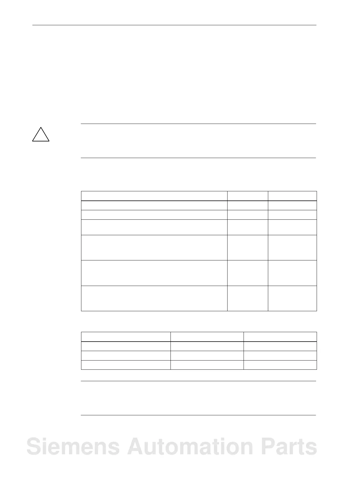
Table 7-2 Electrical parameters of the load power supply for the CNC operator panel (X40) and for
the PP72/48 I/O module (X1)
Parameter
Values Conditions
Voltage range mean value 20.4...28.8 V
Ripple 3.6 Vss
Non-periodic overvoltage 35 V
500 ms duration
50 s recovery time
Rated current consumption
S CNC operator panel
S PP72/48 I/O module
typically 1 A
–
Starting current
S CNC operator panel
S PP72/48 I/O module
2.6A
–
Power consumption
S CNC operator panel
S PP72/48 I/O module
max. 50 W
max. 11 W
Table 7-3 Pin assignment of the screw-terminal blocks X40 (on the PCU) and X1 (on the I/O module)
Terminal
Signal Description
1 P24 24 V DC
2 M Ground (GND)
3 PE Protective earth
Note
Make sure that the interconnecting cable between the power supply and the load power
supply connection does not exceed a maximum length of 10 m (with PP72/48 I/O module
only).
Siemens Automation Parts

 Loading...


