4.3 PP 72/48 I/O module interfaces
Interfaces
4-36
SINUMERIK 802D sl Instruction Manual (BA), 05/2005 Edition
6FC5 397-0CP10-1BA0
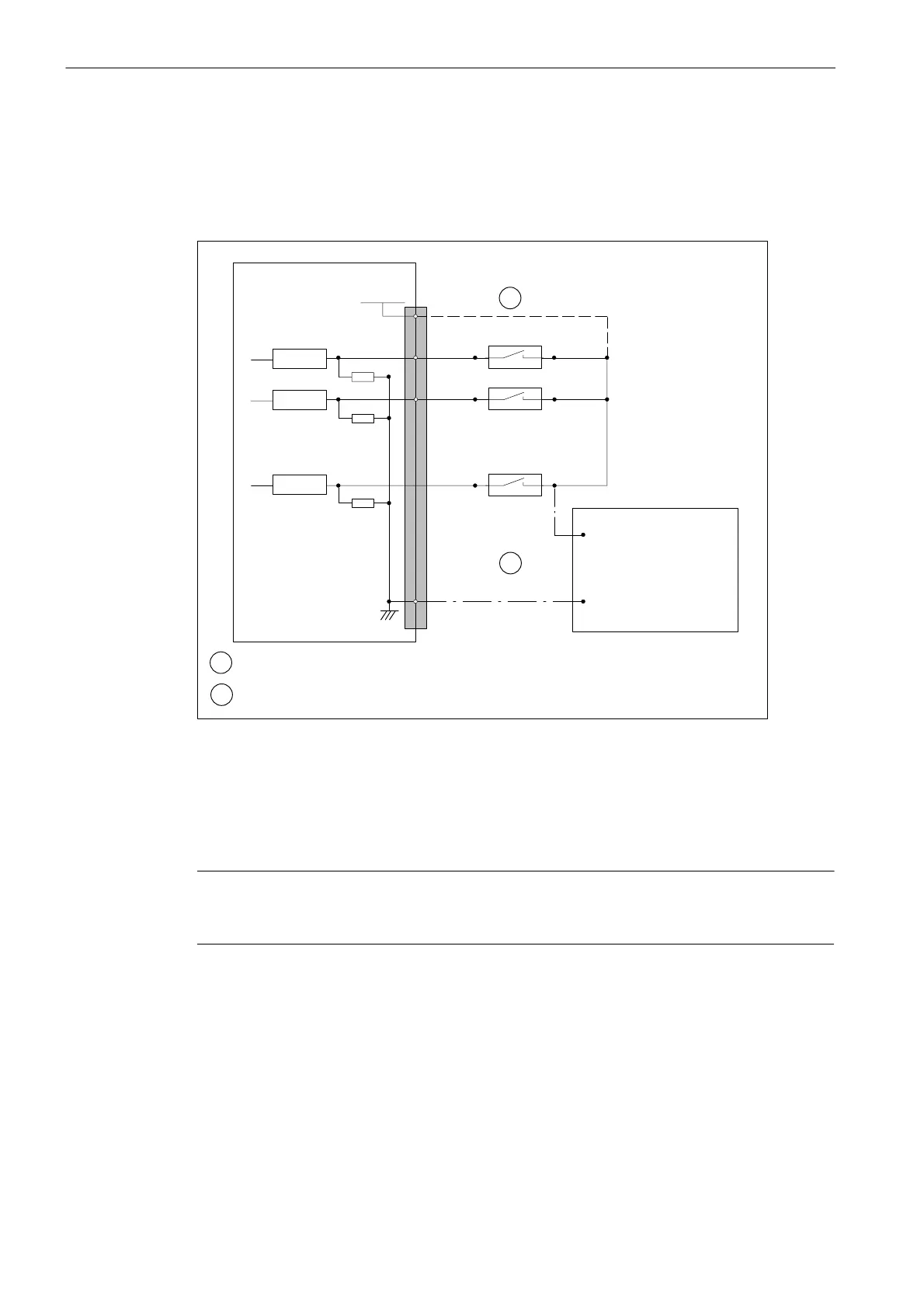
Digital inputs
The diagram below shows the connector pin assignment for the digital inputs at connection
X111 (example). The connector pin assignment of X222 and X333 should be performed
analogously.
PP72/48
X111
Pin number:
2
26
4
3
:
:
:
P24OUT
INT
(+24 V DC)
:
:
:
M
1
24 V DC ext. power
supply
+24 V
0 V
1
Receiver
Receiver
Receiver
2
1
2
when using the internal P24OUT
INT
power supply
when using an external power supply
Fig. 4-5 Connector pin assignment for the digital inputs
Internal power supply (P24OUT
INT
)
The internal power supply for the digital inputs (X111, X222, X333: pin 2) is taken from the
general power supply of module X1, pin 2 (P24).
Caution
Make sure that a max. current of I
out
= 0.25 A at X111, X222, X333 on pin 2 is not exceeded.
Exceeding of the maximum current may destroy the module.
External power supply
If an external power supply is used for the digital inputs, their reference ground must be con-
nected to X111, X222, X333: pin 1 (M).
In this case, X111, X222, X333: Pin 1 (P24OUT
INT
) remains open.

 Loading...


