Interfaces
4.3 PP 72/48 I/O module interfaces
4-35
SINUMERIK 802D sl Instruction Manual (BA), 05/2005 Edition
6FC5 397-0CP10-1BA0
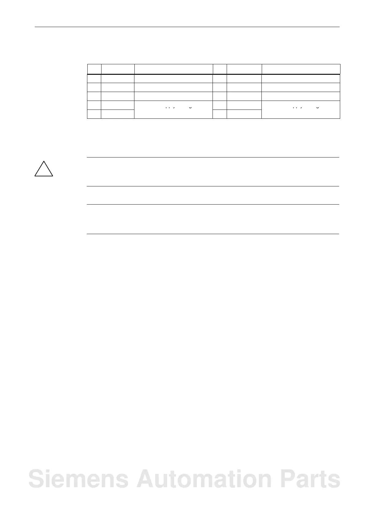
Table 4-13 Pin assignment of the connectors X111, X222, X333, continued
Pin DescriptionNamePinDescriptionName
41 DO n+1.2 Output bit 42 DO n+1.3 Output bit
43 DO n+1.4 Output bit 44 DO n+1.5 Output bit
45 DO n+1.6 Output bit 46 DO n+1.7 Output bit
47 DOCOMx
1)
DC 24 V Supply voltage for 48 DOCOMx
1)
DC 24 V Supply voltage for
49 DOCOMx
1)
the outputs
50 DOCOMx
1)
the outputs
1)
x = 1 for connector X111; x = 2 for connector X222; x = 3 for connector X333
m = 0 for connector X111; m = 3 for connector X222; m = 6 for connector X333
n = 0 for connector X111; n = 2 for connector X222; n = 4 for connector X333
!
Danger
The 24 V power supply is to be designed as functional extra-low voltage with protective
separation in accordance with EN60204-1, Section 6.4, PELV (with M ground).
Note
The connection cable between the voltage source and the load current supply connector
and the associated reference potential M should not exceed a maximum length of 10 m.
Siemens Automation Parts

 Loading...


