4.3 PP 72/48 I/O module interfaces
Interfaces
4-34
SINUMERIK 802D sl Instruction Manual (BA), 05/2005 Edition
6FC5 397-0CP10-1BA0
I/O interface
The following devices can be connected to the connectors X111, X222 and X333 (50-pin rib-
bon-cable plug):
S either one machine control panel (MCP) and one terminal strip converter for digital inputs/
digital outputs (see Fig. 4-3)
or
S three terminal strip converters for digital inputs/digital outputs (see Fig. 4-4)
The terminal strip converters are connected to the PP 72/48 I/O module via ribbon cable.
The individual wiring can be performed at the terminal strips according to your particular
application.
Connector pin assignment
Designation: X111, X222, X333
Type: 50-pin ribbon-cable connector
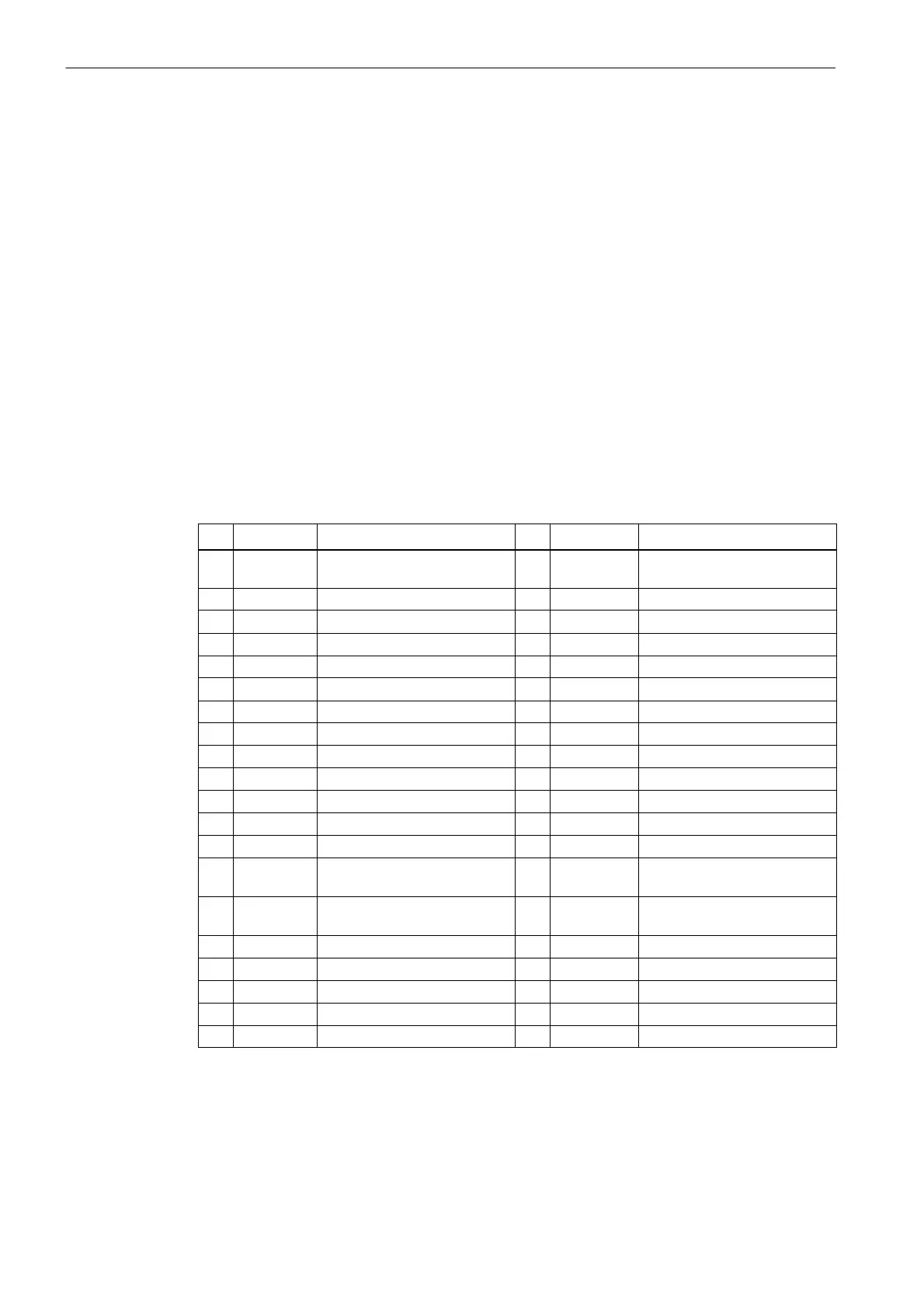
Table 4-13 Pin assignment of the connectors X111, X222, X333
Pin
Name Description Pin Name Description
1 M Ground (GND) 2 P24OUT
INT
DC 24 V, internal supply
voltage for the inputs
3 DI m+0.0 Input bit 4 DI m+0.1 Input bit
5 DI m+0.2 Input bit 6 DI m+0.3 Input bit
7 DI m+0.4 Input bit 8 DI m+0.5 Input bit
9 DI m+0.6 Input bit 10 DI m+0.7 Input bit
11 DI m+1.0 Input bit 12 DI m+1.1 Input bit
13 DI m+1.2 Input bit 14 DI m+1.3 Input bit
15 DI m+1.4 Input bit 16 DI m+1.5 Input bit
17 DI m+1.6 Input bit 18 DI m+1.7 Input bit
19 DI m+2.0 Input bit 20 DI m+2.1 Input bit
21 DI m+2.2 Input bit 22 DI m+2.3 Input bit
23 DI m+2.4 Input bit 24 DI m+2.5 Input bit
25 DI m+2.6 Input bit 26 DI m+2.7 Input bit
27 not
assigned
– 28 not
assigned
–
29 not
assigned
– 30 not
assigned
–
31 DO n+0.0 Output bit 32 DO n+0.1 Output bit
33 DO n+0.2 Output bit 34 DO n+0.3 Output bit
35 DO n+0.4 Output bit 36 DO n+0.5 Output bit
37 DO n+0.6 Output bit 38 DO n+0.7 Output bit
39 DO n+1.0 Output bit 40 DO n+1.1 Output bit
1)
x = 1 for connector X111; x = 2 for connector X222; x = 3 for connector X333
m = 0 for connector X111; m = 3 for connector X222; m = 6 for connector X333
n = 0 for connector X111; n = 2 for connector X222; n = 4 for connector X333

 Loading...


