7.7 Connecting the analog spindle
Connecting
7-60
SINUMERIK 802D sl Instruction Manual (BA), 05/2005 Edition
6FC5 397-0CP10-1BA0
7.7 Connecting the analog spindle
The analog spindle is connected via the X701 interface on the MCPA module.
Analog spindle with directly mounted spindle actual-value encoder (TTL)
The TTL encoder requires an SMC 30 module. For configuring the X520 interface (encoder
connection: TTL with open-circuit monitoring), please refer to the table below.
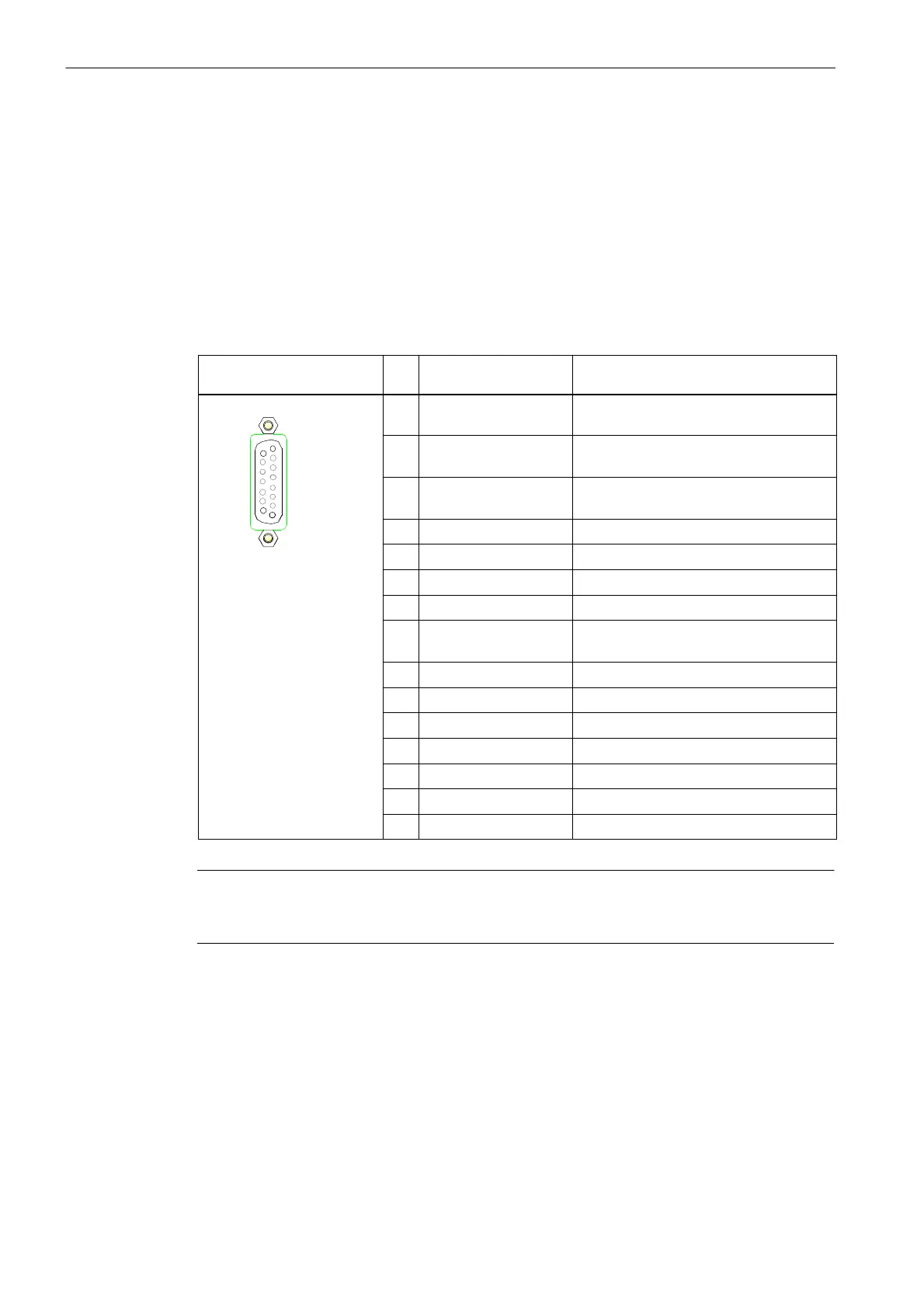
Table 7-1 Assignment of the X520 interface
Description of the female
connector
Pin Name Description
1 Reserved,
not assigned
–
15
2 Reserved,
not assigned
–
3 Reserved,
not assigned
–
1
4 P_Encoder 5 V / 24 V Sensor power supply
X520
5 P_Encoder 5 V / 24 V Sensor power supply
6 P_Sense Sense input sensor power supply
7 M_Encoder (M) Ground for sensor power supply
8 Reserved,
not assigned
–
9 M_Sense Ground sense input
10 R Reference signal R
11 R* Inverted reference signal R
12 B* Inverted incremental signal B
13 B Incremental signal B
14 A* Inverted incremental signal A
15 A Incremental signal A
Caution
The sensor power supply can be parameterized to 5 V or 24 V. The sensor may be
destroyed if you enter the wrong parameters.

 Loading...


