Connecting
7.11 Connecting the RS232 COM port
7-65
SINUMERIK 802D sl Instruction Manual (BA), 05/2005 Edition
6FC5 397-0CP10-1BA0
7.11 Connecting the RS232 COM port
Insert the D-Sub female connectors into connector X8 on the CNC operator panel and into
the connector on the PG/PC. Lock the connector into position using the knurled screws.
Note
Use only shielded lines twisted in pairs; the shield must be connected to the metal or
metalized connector casing on the side of the control system.
The cable set offered as accessories provides maximum interference immunity.
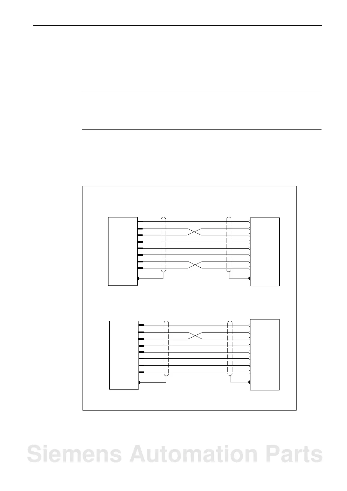
Connection diagram
The diagram below shows the pin assignment of the interconnecting cable between the CNC
operator panel and a PG/PC with 9-pin or 25-pin socket connector.
CNC operator panel (9-pin D-Sub)
PG/PC (9-pin D-Sub)
CNC operator panel (9-pin D-Sub)
PG/PC (25-pin D-Sub)
Shield
Shield
RXD
TXD
RXD
TXD
M
DSR
RTS
CTS
DSR
DTR
2
5
4
3
7
8
CTS
RTS
DCD
DCD
M
DTR
1
6
Shield
Shield
RXD
TXD
RXD
TXD
M
DSR
RTS
CTS
DSR
DTR
CTS
RTS
DCD
DCD
M
DTR
2
7
20
3
4
5
8
6
2
5
4
3
7
8
1
6
2
5
4
3
7
8
1
6
Fig. 7-4 Connection diagram for interconnecting the CNC operator panel and the PG/PC
Siemens Automation Parts

 Loading...


