Interfaces
4.3 PP 72/48 I/O module interfaces
4-37
SINUMERIK 802D sl Instruction Manual (BA), 05/2005 Edition
6FC5 397-0CP10-1BA0
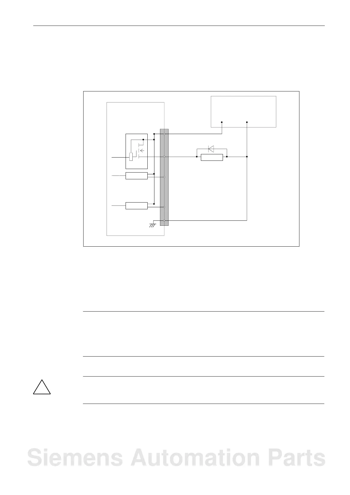
Digital outputs
The diagram below shows the connector pin assignment for the digital outputs at connection
X111 (example). The connector pin assignment of X222 and X333 should be performed
analogously.
Driver
Driver
Driver
:
:
PP72/48
X111
Pin number:
47, 48, 49, 50
(DOCOM1)
M
31
1 (M)
:
:
Relay
24 V DC ext. power
supply
+24 V
0V
32
46
Fig. 4-6 Connector pin assignment for the digital outputs
To supply the digital outputs, an external 24 V DC power supply must be connected to
DOCOMx (X111, X222, X333: pins 47, 48, 49, 50).
The reference ground of the external power supply must be connected to X111, X222, X333:
pin 1 (M).
Caution
It is the user’s responsibility to ensure that the max. current consumption per DOCOMx pin
(X111, X222, X333: pins 47 through 50) does not exceed 1 A.
It is imperative to connect the 24 V power supply for the digital outputs for DOCOMx to all
four pins (X111, X222, X333: pins 47 through 50).
!
Danger
The 24 V power supply is to be designed as functional extra-low voltage with protective
separation in accordance with EN60204-1, Section 6.4, PELV (with M ground).
Siemens Automation Parts

 Loading...


