Connecting
7.12 Connecting the PP72/48 I/O module and the drive
7-67
SINUMERIK 802D sl Instruction Manual (BA), 05/2005 Edition
6FC5 397-0CP10-1BA0
Connecting a bus connector
To connect the bus connector, proceed as follows:
1. Connect the bus connector to the module.
2. Screw the bus connector tight.
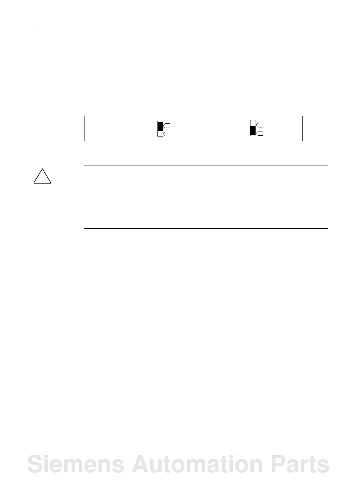
3. If the bus connector is at the start or end of the PROFIBUS DP connection, you must
connect the terminator on the connector (switch position “ON”).
Terminator
connected
Terminator not
connected
on
off
on
off
Fig. 7-5 Bus connector: Terminator connected and disconnected
!
Warning
A bus segment must always be terminated on both ends; otherwise, the data traffic at the
bus could be disturbed.
Make sure that the stations at which the terminator is connected, is always powered, both
during booting and operation.
The terminator is without effect if the last station to which a bus connector is connected is
dead, since the bus connector is powered from the station.
Setting the PROFIBUS DP address
Each bus station must be assigned a PROFIBUS DP address at the PROFIBUS DP for un-
ambiguous identification. Each PROFIBUS DP address must be assigned at the bus only
once.
On the PP72/48 I/O module, the PROFIBUS DP address is set using the DIL switch S1 (see
Fig. 4-3). Use a screw driver to set the PROFIBUS DP address. It results from the addition
of the switches to be found on the right (ON position).
Siemens Automation Parts

 Loading...


