Parameterizing machine data
3.2 Parameterizing the control using machine data
HMI Advanced (IM4)
Commissioning Manual, 03/2009, 6FC5397-0DP10-3BA0
109
Determining the normalization factor
The normalization factor is determined by measuring the spindle using a function generator,
servo trace function, and information in the motor data sheet.
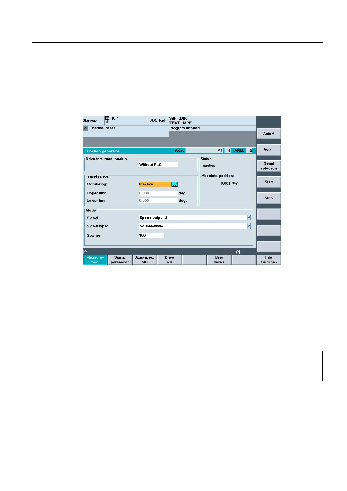
Function generator
Figure 3-4 Function generator
1. Open the following window in the "Start-up" → "Optimization/Test" → "Function Generator"
operating area:
2. In the screen form that appears, select a signal, a signal type and a factor for
normalization under "Mode".
3. Continue by pressing the "Signal parameters" softkey. The "Function generator
parameters" screen form is displayed.
4. Enter the settings for amplitude, cycle duration, pulse width, and limitation. Refer to the
motor data sheet to obtain this data.
NOTICE
If the function generator and measuring function are used on virtual axes, this leads to
an abort by the NCK.