Connection
5.1 Electric
SIPART PS2 with and without HART
Operating Instructions, 10/2013, A5E00074631-11
91
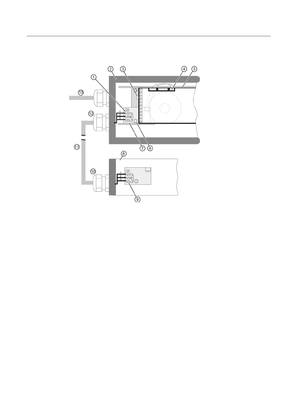
EMC filter module terminals
External position detection system
C73451-A430-D78 or external
Positioner with integral EMC filter module
External position detection system
Yellow wheel for locking the position
External position detection system cable
Ribbon cable connector of fitted
potentiometer, or ribbon cable connector
Cable
EMC filter module cable gland
Input signal for positioner
EMC filter module C73451-A430-D23
Figure 5-22 Connection to positioner
1. Unplug the ribbon cable connector ④ to the fitted potentiometer from the basic
electronics
⑤.
2. Remove the basic electronics
⑤ from the positioner. To this end, remove the two screws
that fix the basic electronics to the pneumatic block.
 Loading...


