Home
Siemens
Industrial Electrical
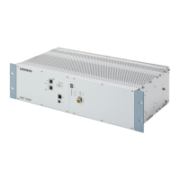
SWT-3000
Siemens SWT-3000 User Manual
5
of 1
of 1 rating
267 pages
Give review
Manual
Specs
To Next Page
To Next Page
To Previous Page
To Previous Page
Loading...
PowerLink 50/100 Equipment Manual
Chapter 3:
Service Program PowerSys and
MemT
ool flash programming
For the Equipment
s PowerLink and SWT 3000
For PowerSys versions
≥
P3.3.25x
PC Features
4
Installation of the service program
4
Menus in the PowerSys
8
Event recorder of the (i)SWT 30
00
18
Firmware upgrade with MemTool
20
113
115
Table of Contents
Table of Contents
3
Functional Description
5
Features at a Glance
6
Applications for Analog And/Or Digital Transmission
7
Applications for Digital Transmission
7
Combination of Analog and Digital Interfaces
8
Transmission Paths
8
FOM (Fibre Optic Modem)
9
Connection to the Powerlink PLC System
9
Connection to a Multiplexer
10
Direct Connection Via Optical Fibre Connection
11
Mode of Operation: Analog
11
Mode of Operation: Digital
12
Features
12
Operating Modes with PLC Equipment
12
Single Purpose Operation
13
Multi-Purpose Operation
13
Alternate Multi-Purpose Operation
13
Equipment Versions
14
Broadband Version
14
Narrow Band Version
15
Applications for Narrow Band Devices
15
Possible Ways of Using the SWT 3000
17
Analog Transmission Path
17
Digital Transmission Path
17
Analog and Digital Transmission Path
18
Integrated into the Powerlink PLC System
18
Monitoring
19
Protection Modes
20
Unblocking Mode
21
Possible Tripping Codes Used in the SWT 3000
21
Description of the Operating Modes Without Unblocking Mode
22
Mode1 (Double System Protection)
22
Mode2 (Single-Phase Protection)
22
Mode3 (Four Commands with Priority)
23
Mode 3A (Four Independent Commands 4Ic)
23
Mode 3B (2Plus2)
24
Mode4 (Only One Commands Active)
24
Mode 5A "3 Commands Independent
25
Mode 5D (Only for Digital Line Interfaces LID)
26
Description of the Operating Modes with Unblocking Mode
27
Mode1 (Double System Protection)
27
Mode2 (Single-Phase Protection)
27
Mode3 (Four Commands with Priority)
28
Mode 3A (Four Independent Commands 4Ic)
28
Mode 3B (2Plus2)
29
Mode4 (Only One Commands Active)
29
Mode 5A "3 Commands Independent
30
Mode 5D (Only for Digital Line Interfaces LID)
31
Frequency Overview
32
Broadband Devices in the VF Range [Khz]
32
Narrow Band Devices in the VF Range [Khz]
32
Frequency Diagram for Broadband and Narrow Band Devices
33
Command Duration for Single Purpose Operation
34
Double System Protection
34
Single-Phase Protection Resp. Operating Mode 4 and M5A
34
Switching Functions Mode 3
34
Mode 3A, 3B Resp. 5A
34
Command Duration for Alternate Multi Purpose Operation
34
Remote Monitoring (RM) and Service Channel
35
RM with Analog Interface
35
RM with Digital Interface
36
Service Channel
36
The IP Network - Your Gateway to SWT 3000
38
Power Supply
39
Stand-Alone Unit
39
Integrated Unit
39
Index
40
Equipment Manual Swt 3000 Chapter 2: Installation and Commissioning
44
General Safety Regulations
46
Transport and Storage
47
Installation
48
Equipment Manual
49
Installation Procedure
49
Cabling and Equipment
49
Grounding
49
Connecting the Device Without FOM Modules
50
Connecting Plugs
50
Equipment of the Sub Rack Without FOM Slots
51
Connecting the Device with FOM Modules
52
Connecting Plugs
52
Equipment of the Sub Rack with FOM Slots
53
Pin Assignments of the SWT 3000 Modules
54
Pin Assignment of the IFC-X Module
54
Pin Assignment of the Pu3F Module
55
Signals of the Line Interface Analog (LIA)
56
Connection of the Digital Line Interfaces
56
Signals for the LID-1 (Line Interface Digital 1)
57
Signals for LID-2 (Line Interface Digital 2)
58
Service Channel Interface
58
Remote Access Interface SSR
58
Remote Monitoring (RM) Interface SSB
59
Pin Assignment of the CLE Module
59
Pin Assignment of the ALRS Module
60
Pin Assignment of the ALR Module
61
Jumper Settings for the SWT 3000 Modules
62
Jumper Settings for the Pu3F Module
63
Links for Selecting the Line Interfaces LID-1
64
Links for the Selection of Line Interfaces LID-2
64
Selection of the Input Gain for the G703.6 Interfaces
64
DLE Settings for the LID-X Connection Via FOM
64
Jumper Settings for the CLE Module
65
Jumper Settings for the FOM Module
66
The Fobox
67
Interfaces of the Fobox
67
Power Supply of the Fobox
68
Alarm Relay Contacts of the Fobox
68
Signification of the LED
68
Jumper Settings of the FOB
69
ALR Module
70
Visual Indication
70
Test Switch S1
70
Jumper Settings for the ALRS Module
71
ALR Jumper Settings
72
Commissioning
73
Switching on the Power Supply
73
Switching on the Device
73
Connecting the Service
73
PC Requirements
73
PC Connecting Cable
74
Settings on the Device
75
Setting of the SWT 3000 Transmit Level
75
Operation with the PLC System Powerlink
76
Connection Via a Vfx Module
76
Connection of an External SWT 3000 to the Powerlink50/100
77
Connection Via a FOM Module
78
Pu3F Integrated in the Powerlink
80
Connection of Two SWT 3000 Via FOM
81
System Configuration
81
Connection of the SWT 3000 Via FOM to a Multiplexer
82
System Configuration
82
Receive Level for Analog Interfaces
83
Setting Parameters of Measuring Points
84
Time/Date
85
Clock Synchronisation
85
Line Clock Synchronisation
87
SWT 3000 New Configuration
88
Configuration
88
System Configuration
89
Selecting the Operating Mode
90
Selecting the Connection Interface
90
SWT 3000 <System-2 Configuration
91
Interfaces
91
Power Supply
91
Test Mode
91
Application
92
Output Allocation
92
SWT 3000 <RM> Configuration
93
Setting Options for the SWT 3000 <Timer> Configuration
94
Configuration of the Command Input Resp. Output
95
Timer Settings for the Command Output
98
Setting Recommendations for the SWT 3000 Timer Configuration
100
Broadband Versions
100
Narrow Band Versions
102
Programming the Device
102
SWT 3000 Alarms
103
Alarm Output Via the ALRS or ALR Module
103
Alarms on the CLE
103
Possible Reasons for the Alarms
104
Special Features for the Output of the Unblocking Impulse
105
Stand Alone Equipment
105
SWT 3000 Integrated in the ESB 2000I
105
SWT 3000 Integrated in the Powerlink System
105
Setting Options for the SWT 3000 <Alarms
106
Configuration of the Alarm Output RXALR in the Powerlink
107
Alarm Messages in the Service Program Powersys
107
Index
108
Appendix
110
List of Figures
110
List of Tables
112
Table of Contents
115
Service Program Powersys
117
PC Requirements
117
Installation of the Service Program
117
Starting the Service Program
118
The Menu Options
119
Create System Log
119
Connection
120
The Powersys Menu
121
Print Preview
121
FW Package Import / Export
122
The <Data Source> Menu
123
Data Source <Device
123
Data Source <File
123
Data Source <New
124
Data Source <Remote Device
125
The <Firmware> Menu
125
Firmware <Download
125
Firmware <Dongle Upgrade
126
Considerations before Dongle Upgrade
126
Dongle Upgrade on Site
126
Display after the Connection Has Been Established
128
The Form <Commands
129
The Iswt3000 Event Recorder
131
General Information
131
Display of the Entries in the Event Recorder
132
Firmware Upgrade with Memtool
133
General Information
133
System Requirements
133
Version of Memtool
133
Installation of Memtool
134
Basic Settings
135
Starting Memtool
135
Memtool Settings
135
Getting Started
138
Programming of Flash Memory in the Powerlink
139
Connecting the
139
Starting Memtool
140
Connection to the Powerlink Target
141
Programming the Application into the Flash Memory
141
Powersys Release Upgrade Check
144
Powersys Release
144
Programming of Flash Memory in the Powerlink Vmux
145
Connecting the
145
Starting Memtool
146
Connection to the Vmux Target
147
Programming the Application into the Flash Memory
147
Powersys Release Upgrade Check
150
Powersys Release
150
Programming of Flash Memory in SWT 3000
151
Connecting the
151
Starting Memtool
152
Connection to the SWT 3000 Target
153
Programming the Application into the Flash Memory
153
Powersys Release Upgrade Check
155
Powersys Release
155
Trouble Shooting
156
Index Directory
157
Appendix
158
List of Figures
158
List of Tables
159
Swt 3000 Equipment Manual Chapter 4: Interface Modules
161
General
162
Exclusively Analog Transmission Interface or Analog Secondary Path
162
Exclusively Digital Interfaces
162
Description of Operation
162
Connection Principle
163
Controller
165
Test Input
165
Displays
165
Slot and Module Identifier
166
Signal Acquisition through the Binary Inputs
167
Signal Output from the IFC-D/P Module
168
Signal Output from Module
169
The Interface Modules IFC
162
Technical Data for Modules IFC-D/IFC-P
174
Supply Voltages
174
Working Temperature Range
174
Internal Interface IFC Bus
175
Binary Inputs IFC-D
175
Relay IFC-D
175
Relay
175
Mechanical Data IFC-D/IFC-P
175
Index
176
Appendix
177
Swt 3000 Equipment Manual Chapter 5: Pu3F Module
179
Functions of the Pu3F Module
180
Mode of Operation of the Pu3F
183
Internal Power Supply
183
Controller
183
The Analog Line Interface (LIA)
183
Self-Test
184
Control and Display Elements of the PU3
184
Significance of the Leds on the PU3
185
Service Interface
186
Operating Mode as Stand-Alone SWT 3000
186
Operating Mode as Integrated SWT 3000 (Iswt)
186
Interference Level Evaluation
187
Event Memory and Real-Time Clock
187
Clock Synchronisation
187
Line Clock Synchronisation
189
The Digital Line Equipment DLE
190
Transmission Concept
190
Line Interface X.21
191
Line Interface G703.1 (64 Kbit
192
Line Interface G703.6 (2Mbit/S HDB3)
193
Jumper Settings
193
Index
194
Appendix
195
Swt 3000 Equipment Manual Chapter 6: Cle Module
197
Description of Operation
198
The Receive Section
199
The Transmit Section
199
Alarm Displays
200
S6 Control Wires
201
Test Sockets
201
Inhibit Line
201
Jumper Settings
202
Connector Pin Assignment of the CLE
203
Connecting Cable to the PLC Unit ESB 2000I
204
Vfx Port 3
204
Index
206
Appendix
207
Swt 3000 Equipment Manual Chapter 7: The Alarm Modules Alrs and Alr
209
Input and Outputs
210
Operating the Signaling Relay
210
Binary Input Clock Synchronization
210
Supply Voltages
211
Jumper Settings
212
Pin Assignment X1 of the ALRS
213
Function of the ALRS
210
The ALRS Module
210
The ALR Module
214
Block Diagram
214
Binary Inputs
215
Relay Outputs
215
Visual Indication
215
Pin Assignment X1 of the ALR
217
Index
218
Appendix
219
Swt 3000 Equipment Manual Chapter 8: The Power Supply
221
General Description
222
Functional Description
223
Technical Data
223
Displays
225
Connection of the Power Supply
226
Redundant Power Supply
227
Inhibit Loop
228
Index
229
Appendix
230
Swt 3000 Equipment Manual Chapter 9: Technical Data
232
Command Input/Output
233
Input IFC-P/IFC-D
233
Command Output IFC-P
233
Command Output IFC-D
233
Signaling Output IFC-S
233
Transmission Via Analog Network
234
Modulation Type
234
Broadband Equipments
234
Narrowband Modulation
234
Transmission Time (SWT 3000 Stand Alone)
235
Transmission Time (SWT 3000 Integrated into Powerlink)
235
SWT 3000 Fibre Optic Module FOM
236
Technical Data Fobox
236
Security
237
Dependability
237
Voice Frequency Interface CLE
237
Transmission Via Digital Networks
234
Digital Interface
234
Transmission Time
234
Security
234
Dependability
234
Power Supply
237
Input Voltage
237
Power Consumption
237
Alarm Output ALRS Module
238
Alarm Output ALR Module
238
Binary Input ALR Module
238
Clock-Synchronization Input
238
Network Management
238
Mechanical Design
239
Dimensions
239
Weight
239
Insulation Withstand Voltage
240
Impulse Withstand Level 1,2/50Μs
240
Climatic Conditions
240
Mechanical Conditions
240
Service PC
239
Electromagnetic Compatibility EMC
239
Immunity
239
Emission
239
International Standards
240
Swt 3000 Equipment Manual Chapter 10: Snmp and Remote Access
242
General Safety Regulations
243
Transport and Storage
244
Installation
245
Equipment Manual
246
Installation Procedure
246
Grounding
246
Overview Remote Access and Remote Monitoring
247
1 Remote Access Via Intranet (TCP/IP)
247
2 Remote Access Via Modem
247
3 Remote Monitoring Via In-Band RM Channel
247
Snmp
248
General Information
248
SNMP Function
248
Functional Diagram
249
Polling of the SWT 3000 Device Data
250
SWT 3000 Read General Information
250
SWT 3000 Read Hardware Configuration
250
SWT 3000 Set Commands
250
Spontaneous Indication SNMP Traps
251
General Traps
251
SNMP Agent Specific Traps
251
SWT 3000 Alarms
252
Installation of the SNMP
253
Connection Principle of the SNMP Server
253
Installation Instructions for the SNMP Adapter in a SWT 3000 Device
254
Commissioning SNMP
256
LED Indicators
256
RS232 Interface
256
Activated Ports
256
IP Address
256
Web Login
257
SWT 3000 Remote Access
260
General Information
260
Remote Access Examples
261
Index Directory
265
Appendix
266
5
Based on 1 rating
Ask a question
Give review
Questions and Answers:
Need help?
Do you have a question about the Siemens SWT-3000 and is the answer not in the manual?
Ask a question
Siemens SWT-3000 Specifications
General
Brand
Siemens
Model
SWT-3000
Category
Industrial Electrical
Language
English
Related product manuals
Siemens SIRIUS 8WD44
5 pages
Siemens SIVACON 8PS LD
5 pages
SIRIUS 3ZX1012-0RT02-1AA1
4 pages
SITOP power DC-UPS Module 15
8 pages
Siemens 3VT
15 pages
Siemens RCD110
15 pages
Siemens 3VA2 Series
10 pages
Siemens 7XT34 Series
28 pages
Siemens RAJA+ 3TE7421
8 pages
Siemens 3VA9467-0FK21
10 pages
Siemens 3VA9157-0FK21
10 pages
Siemens 6SL3351-1AE33-1AA2
3 pages