PU3 Module SWT 3000 Equipment Manual
Page - 4 Edition p3_3_2x 08/09 © SIEMENS AG 2008
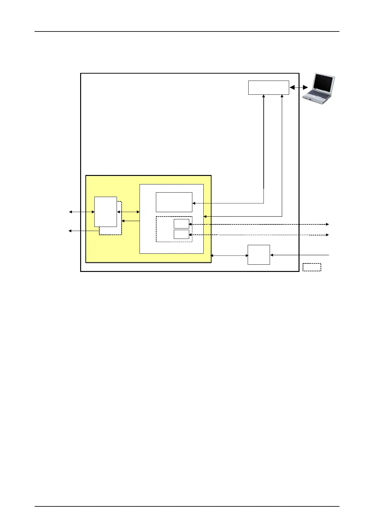
If the PU3 and the IFC modules are integrated in the PowerLink unit the frequencies are for-
warded to the CSP module via the SSI.
Option
LIA
DLE
IFC-1
PU3f
LID-1
LID-2
IFC-2
iSWT3000
PowerLink
CSP
PS
LAN
X.21/G703.1/G703.6
X.21/G703.1/G703.6
Service PC
SSI
PU3f Processor module CSP Central signal processing module
IFC Interface module LID Line interface digital
PS Power supply DLE Interface module to digital
transmission paths
Figure 2: Block diagram of the SWT 3000 unit integrated in the PowerLink.
At the receive end the incoming commands are received in the VF range resp. digital depending
on the operating mode, converted into ”binary” protection commands and forwarded to the IFC-D/P
module for command output.
Apart from coding and decoding of protection commands the PU3f also performs various moni-
toring functions. For example, the receive and transmit levels are fed via measuring points to the
PU3f where they are compared with the permissible values. If these levels are not reached the
PU3f activates an alarm. In the normal situation, i.e. if there is no protection command to be trans-
mitted the guard signal is sent to the distant station.
Loss of a wanted signal (command or guard tone) triggers an alarm at the receive end and
causes the relay outputs of the device to block. This alarm state can only be cancelled by receiving
the guard signal again.