SWT 3000 Equipment Manual Power Supply
© SIEMENS AG 2006 Edition p3_3_x 08/09 Page - 5
Control circuit: The control circuit monitors the output voltage U
01
and generates the
control signal for the switching transistor on the primary side taking into
account the maximum permissible output currents. The control signal is
fed back to the switching transistor via a transformer for the purpose of
electrical isolation. The secondary outputs U
02
and U
03
are controlled
individually and independently and each have their own current limiting
system. If one of the secondary outputs is operating in current limiting
mode the voltages of the other outputs are also reduced.
Fuse: A fuse holder mounted on the rear of the unit holds a 5x20mm fuse which
protects the unit against major damage. For input voltages >
200 V DC
an external fuse or a protection switch at system level is recommended
additionally.
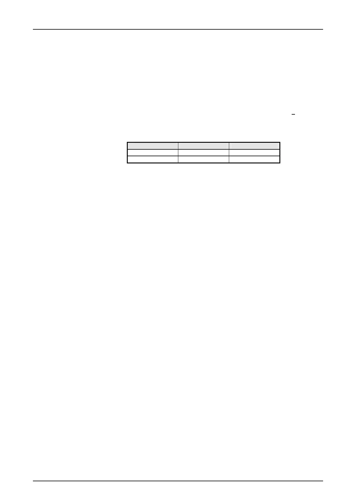
Table 2: Fuses used in the converter types
Converter type Fuse Fuse type
SVB4 slow-blowing 8 A / 250V
SVN4 slow-blowing 4 A / 250V
Disconnection: An internal inhibit signal disconnects the outputs below about 0,8*Umin
and above about 1.1*Umax.
Inrush current: When switching on for the first time an NTC thermistor in the input circuit
reduces the inrush current surge by a factor of about 5...10. This protects
connector junctions and switches against possible damage. Repeated
start-up operations at short intervals reduce the effect of the NTC with the
result that the inrush current surge increases.
Inhibit input: The inhibit input enables the output voltages to be switched on and off by
means of logic signal U
inh
(TTL, CMOS). If this function is not used the
inhibit input (No. 2) must be connected to the minus pole of output
1, (No. 23) in order to enable the outputs. This connection is routed via
the module slots in the SWT 3000 system. If a module is removed or not
correctly installed the power supply to the unit is disconnected.
Installation: The power supply connection must comply with the regulations in force in
the particular country. Only the socket connector (Fig. 8.3 ) is to be used
for the cabling. Other types of connection do not guarantee compliance
with the safety regulations in every case. The units correspond to protec-
tion class I. Installations in compliance with protection class II require ad-
ditional insulating access protection around the housing of the power
supply. If a second fuse is necessary this must be provided in the incom-
ing line to terminal no. 29 of the power supply unit.
 Loading...


