Digital inputs and outputs
AG25, AG26 Date: 09.07.2018 Art. No. 88094 Mod. status 225/18 Page 13 of 109
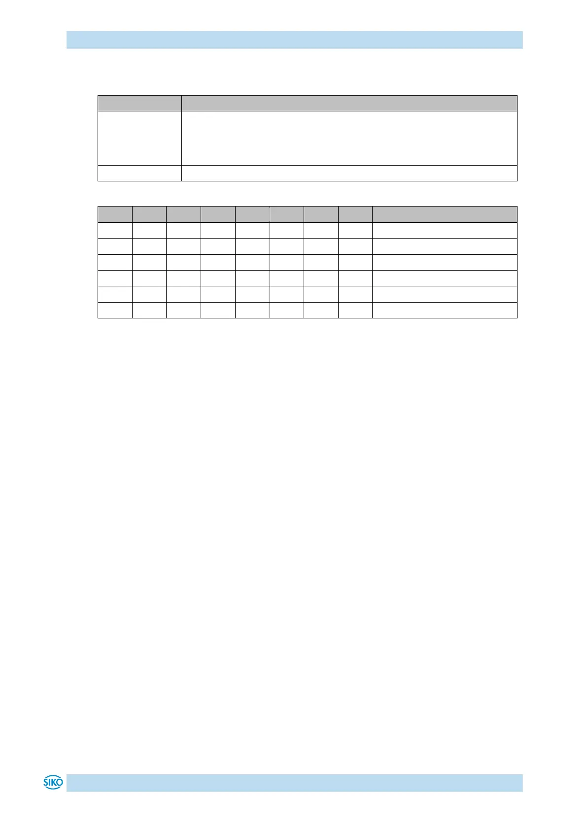
2.3.2 DIP switch:
Setting of low byte of the 2-byte device ID in binary format
The high byte of the device ID is always 00h.
0 = not configured
1 … 255 = device ID
You can assign an “Explicit Device ID” to the actuator by means of the DIPswitch, enabling
addressing independent of the physical position in the network.
3 Digital inputs and outputs
The actuator has four configurable digital inputs and one configurable digital output.
Function and switching behavior can be set.
No function has been assigned to the digital inputs in the factory setting.
The logical status of the digital inputs is mapped in the process data independent of the
assigned function.
If a function was assigned to the digital input, the functional conditions of the digital inputs
can be read in the register Digital Input Functionalities State (Object 2405h).
With factory settings, the digital output can be actuated via the process data.
If a function is assigned to the digital output, it is actuated via register Digital Output
Functionalities State (Object 2302h).

 Loading...
