Functional description
AG25, AG26 Date: 09.07.2018 Art. No. 88094 Mod. status 225/18 Page 18 of 109
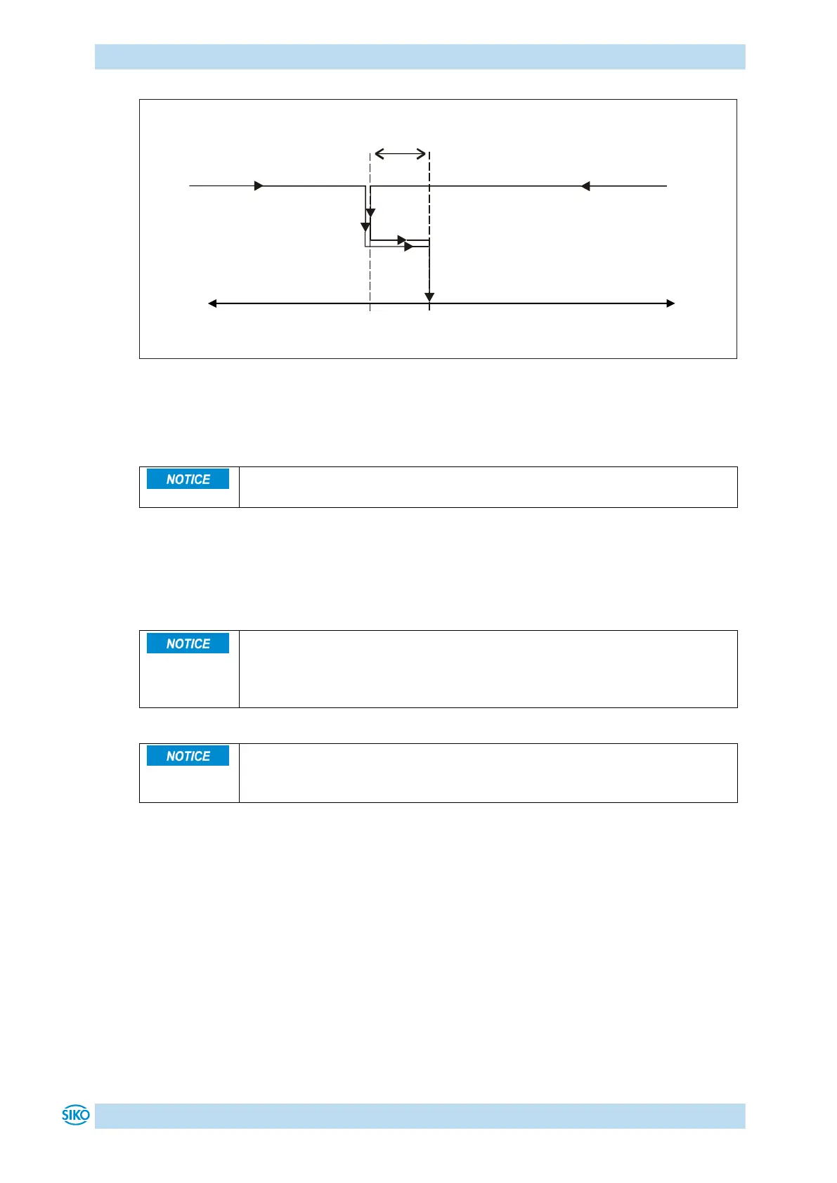
Fig. 7: Loop+ positioning
4.1.1.2 Inching mode
There is no compensation for spindle backlash (loop positioning) in this
operating mode.
Inching mode is enabled in the positioning mode only. You can program via parameters
acceleration as well as speed in the inching mode.
4.1.1.2.1 Inching mode 1
If the Spindle pitch parameter is programmed to zero, then the traveling
distance occurs by steps. If Spindle pitch is unequal zero, then the
information of the Delta Tipp parameter refers to the travel distance in
1/100 mm.
If the actual position is outside the programmed limiting values, then
traveling from this position in the respective direction must be performed
by means of inching mode 1 or 2!
The drive travels once from the current actual position by the value Delta Inch (Object 2611h)
depending on the mathematical sign of the value entered.
Delta Inch < 0: negative travel direction
Delta Inch > 0: positive travel direction
Reaching of the target position will be indicated accordingly.
A digital input can be configured for starting inching mode 1.
The following conditions must be met for enabling the start of inching modes 1 and 2:
Supply voltage of the output stage is applied.
Operation enabled
Drive stands still
Positioning in positive
direction
Positioning in negative
direction
Loop Length (Object 2617h)