Functional description
AG25, AG26 Date: 09.07.2018 Art. No. 88094 Mod. status 225/18 Page 23 of 109
4.1.3 Limit switch
Two digital inputs must be configured correspondingly if the limit switch function is to be
used.
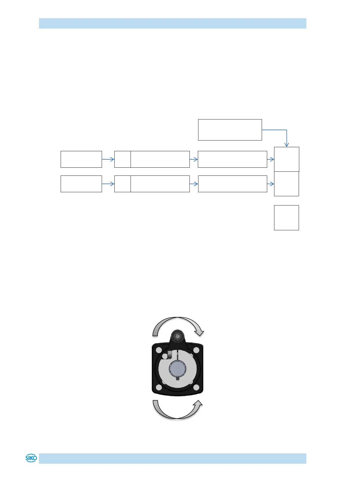
4.1.3.1 Example of limit switch configuration
Exemplary configuration for the connection of proximity switches DC PNP NC.
Fig. 10: Example of limit switch configuration
4.1.3.2 Arrangement of the limit switches
The limit switches are arranged according to the following pattern independent of the
configured sense of rotation:
Fig. 11: Arrangement of the limit switches
Digital Input 1 Functionality
Object 2401h, value = 1
Digital Inputs Polarity
Object 2406h, bit 0 = 1
Bit 1
Digital Inputs Polarity
Object 2406h, bit 1 = 1
Digital Input 2 Functionality
Object 2402h, value = 2
Digital Input Functionalities
State
Bit 0
Bit 31