Digital inputs and outputs
AG25, AG26 Date: 09.07.2018 Art. No. 88094 Mod. status 225/18 Page 14 of 109
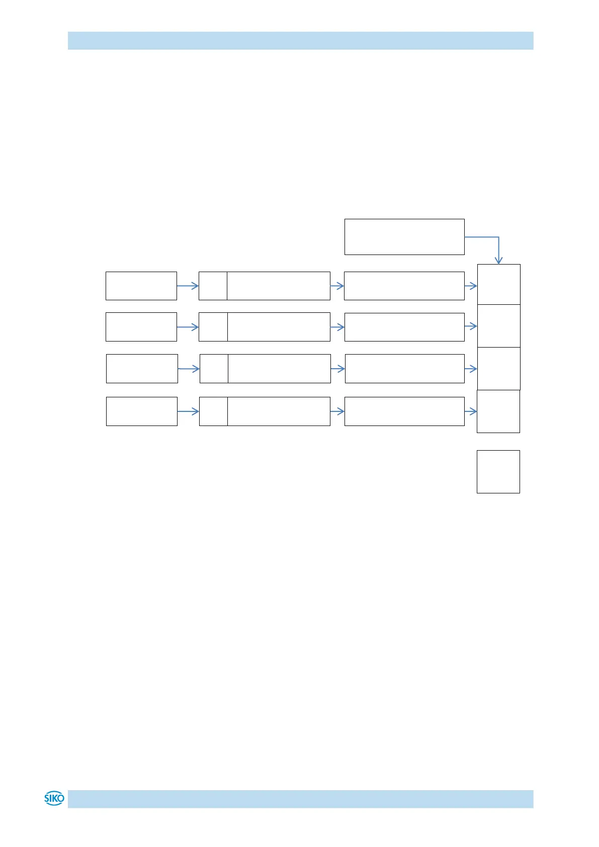
3.1 Examples of digital input configurations
The following configuration deviates from the factory setting and requires parameterization by
the user.
Digital input 1: Limit switch 1 (low-active) proximity switch DC PNP NC
Digital input 2: Limit switch 2 (low-active) proximity switch DC PNP NC
Digital input 3: Inching mode 2 positive travel direction (high-active) pushbutton
Digital input 4: Inching mode 2 negative travel direction (high-active) pushbutton
Fig. 3: Examples of digital input configurations
Digital Input 1 Functionality
Object 2401h, value = 1
Digital Inputs Polarity
Object 2406h, bit 0 = 1
Bit 0
Bit 1
Bit 2
Bit 3
Digital Inputs Polarity
Object 2406h, bit 1 = 1
Digital Input Functionalities
State
Digital Input 3 Functionality
Object 2403h, value = 3
Digital Inputs Polarity
Object 2406h, bit 2 = 0
Digital Input 4 Functionality
Object 2404h, value = 4
Digital Inputs Polarity
Object 2406h, bit 3 = 0
Bit 31
Digital Input 2 Functionality
Object 2402h, value = 2

 Loading...
