120 • Trouble Shooting
_____________________________________________________________________________________________
14. TROUBLE SHOOTING
The following procedures should be done only upon fault and in case trouble shooting is required.
14.1 In-Out Resistance and Cathode-Cathode Resistance
Verify that the motor is disconnected.
Disconnect the cabinet mains isolator switch or fuses, if installed.
In-Out resistances should be the same for all three phases in each model. Cathode-Cathode
resistances are indicated in the following table:
HRVS-DN Rated
Voltage
L1 – U
L2 - V
L3 - W
Cathode-Cathode
2.3kV 1.2MΩ ±10% 1/2 of In-Out resistance
3.3kV 135kΩ ±10%
1/3 of In-Out resistance
4.16kV 135kΩ ±10%
6.6kV 300kΩ ±10%
10kV 420kΩ ±10%
1/5 or 1/6 of In-Out
resistance. (depends
on number of thyristors
in the soft starter)
11kV 450kΩ ±10%
13.2kV 500kΩ ±10%
13.8kV 500kΩ ±10%
15kV 550kΩ ±10%
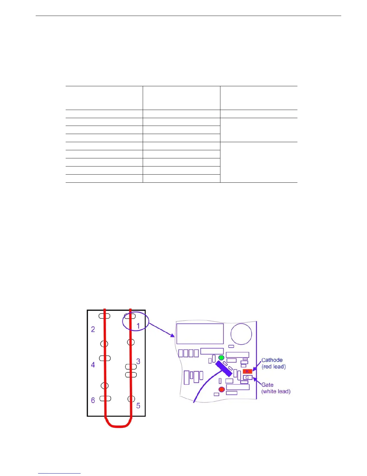
Refer to Figure 50 In order to identify the Cathode terminals of all 6 SCRs on the firing PCB.
A number is written on the firing PCB to identify the SCRs.
Measure Cathode-Cathode resistances as follows:
Cathode SCR#1 to Cathode SCR#2 (should be 1/3 of L1-U, L2-V, L3-W)
Cathode SCR#2 to Cathode SCR#3 (should be 1/3 of L1-U, L2-V, L3-W)
Cathode SCR#3 to Cathode SCR#4 (should be 1/3 of L1-U, L2-V, L3-W)
Cathode SCR#1 to Cathode SCR#4 (should be same as L1-U, L2-V, L3-W)
Verify that values correspond to the above table.
14.2 Rgk (thyristors Gate-Cathode) Resistances.
Thyristors Gate-Cathode resistances can easily be measured from the firing PCBs.
In order to access the testing points the front cover of the Power Section needs to be dismantled.
Gate-Cathode connection points of SCR#1 are illustrated in Figure 50. Measure all SCRs’ Rgk
resistances in each of the phases.
Rgk values should be about the same for all thyristors in the phase, and in the range of 7-20 Ω.
Figure 50 – Firing PCB – SCR#1 Gate-Cathode Testing
 Loading...


