89 • Commissioning and Operation Manual
_______________________________________________________________________________________________
You are only allowed to open the low voltage compartment door and customer terminal compartment door
when medium voltage is connected to the cabinet!
It is strictly forbidden to open the medium voltage compartment door at any time when medium voltage is
connected to the cabinet!
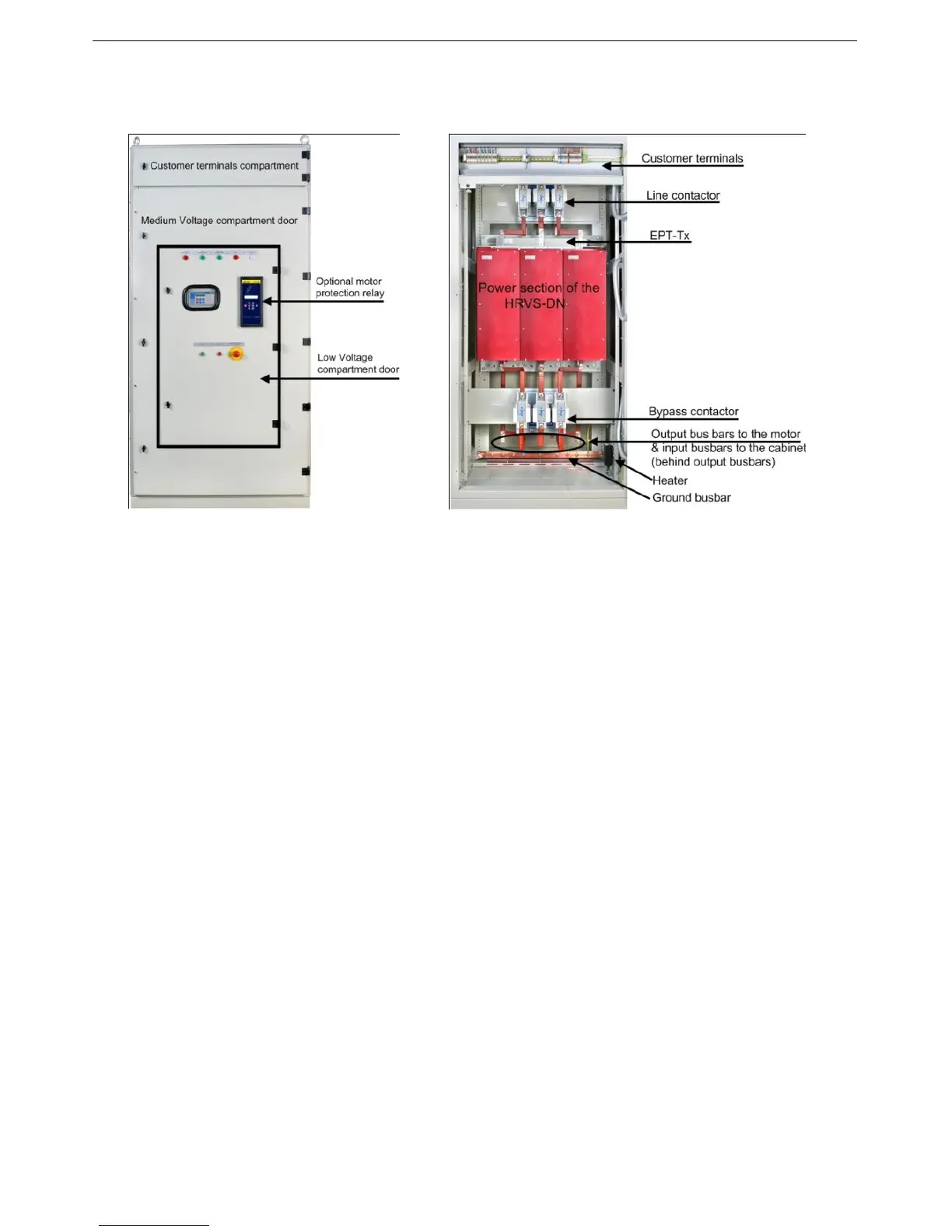
Figure 29 - HRVS-DN up to 6.6kV Standard
Cabinet – Doors Closed
Figure 30 - HRVS-DN up to 6.6kV Standard Cabinet –
Doors Open
View with medium voltage door open and customer terminals compartment door:
Customer terminals are located in a dedicated compartment on the top of the cabinet.
Line Contactor is mounted on the top of the medium voltage compartment.
The EPT-Tx (Electronic Potential Transformer Transmitter) is mounted on the medium voltage bus
bars downstream the Line Contactor on the input to the Power Section of the HRVS-DN thus
measuring the input voltage to the Power Section.
The output of the EPT-Tx are two fiber optic wires running to the EPT-Rx (Electronic Potential
Transformer Receiver) which is located in the low voltage compartment.
The harness runs out of the Power Section to the low voltage compartment. This harness includes
both fiber optic wires and copper wires.
The main unit is the Power Section of the soft starter.
Note that this Power Section is actually composed of three identical modules, one per phase.
The input bus bars to the Power Section are on top of it marked L1,L2, L3.
Two sets of three bus bars each are mounted at the bottom of the Power Section:
o One set, marked L1B,L2B,L3B, is connected to the input bus bars of the Power Section. These
bus bars are brought to the bottom of the Power Section to enable convenient connection of the
Bypass Contactor.
o Second set, marked U,V,W, is the output bas bars.
At the bottom of the cabinet the Bypass Contactor is located.
Verify on cabinet label that both, medium voltage and control voltage, are according to the supplied
mains voltage and control voltage.
Input bus bars and output bus bars are located at the bottom of the cabinet.
The input bus bars are at the back of the lower part of the cabinet.
The output bus bars are at the front of the lower part of the cabinet.