43 • Installation of IP00 (OEM Kit) in a Cabinet
_______________________________________________________________________________________________
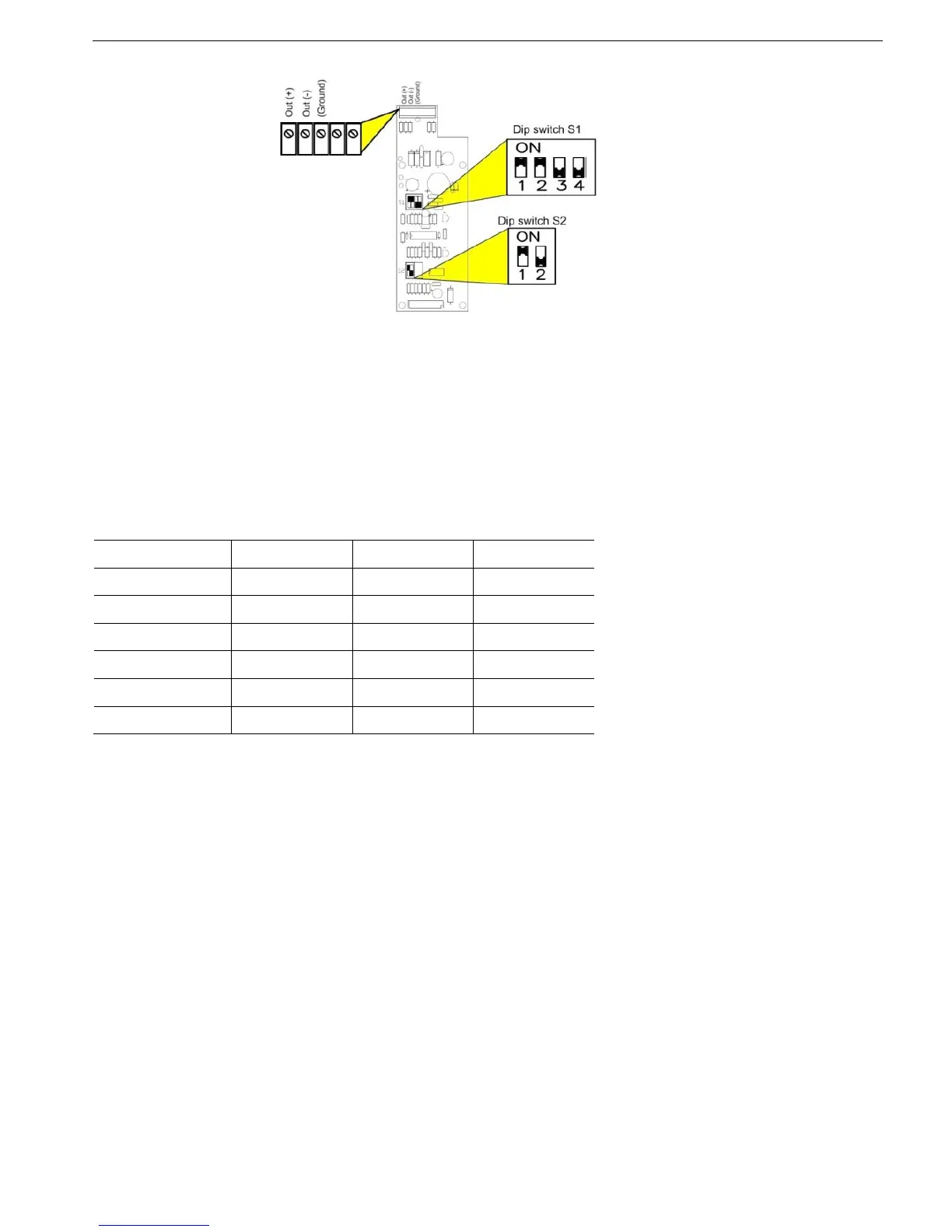
6.5 Analog I/O (Option 5) (Terminals Gnd, Out (-), Out (+))
Figure 16 – Optional Analog PCB
Analog PCB is located on the upper right side of the control nodule.
(Refer to Figure 15 page 10)
Ground Terminal (terminal Gnd)
Leave this terminal not connected. Ground the shield of the analog output signal at the recipient side.
Analog Output (Terminals Out (+), Out (-))
Dip switches allow selection between: 0-10VDC, 0-20mA, 4-20mA
The analog value is related to I, 0….200% of FLA or 0….200% of RATED MOTOR PWR .
Refer to section
7.8.7 on page 73 for ANALOG OUTPUT programming.
Switch No. 4-20 mA* 0-20 mA 0-10VDC
S1- Switch # 1 On On Off
S1 - Switch # 2 On On Off
S1 - Switch # 3 Off Off On
S1 - Switch # 4 Off Off On
S2 - Switch # 1 On Off Off
S2 - Switch # 2 Not used Not used Not used
* Factory default setting