110 • Test Procedure for Low Voltage Testing
_____________________________________________________________________________________________
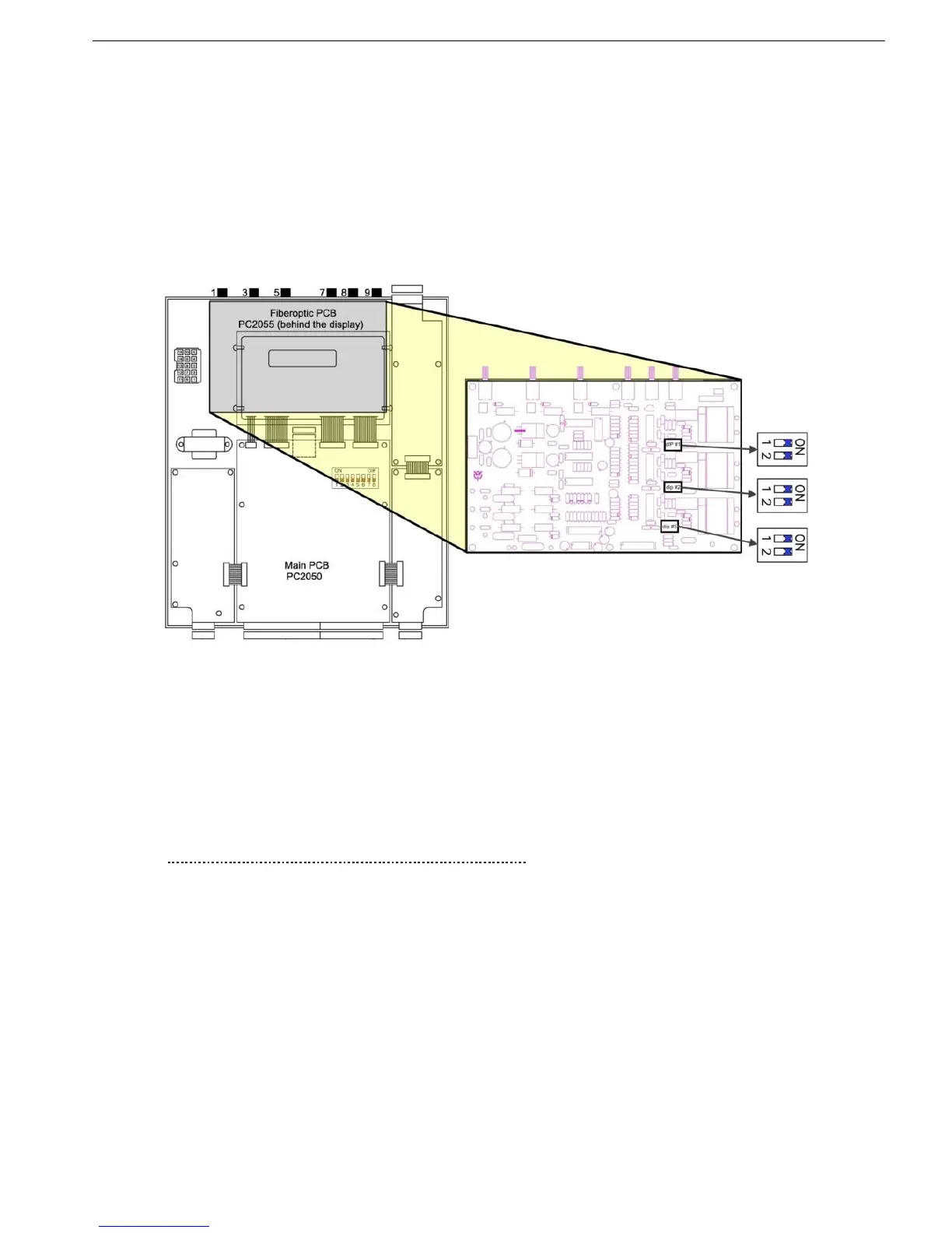
12.3.1 Current Gain Dip Switches Setting
The unit is factory calibrated to the rated current of the starter. For example, if the STARTER FLC is 320A and
the rated current of the low voltage motor used for testing is 15A. The ratio between these current values is
21.3. In order to enable testing with that low level of current, additional gain should be added to the current
path. To do so, loosen the four screws holding the display case that covers the upper Printed Circuit Board
(PCB). Slide out the top while the two bottom screws are used as a shaft. On the right side of the PCB, there
are three couples of Gain dip switches. Each pair is for a single phase. Note that all Gain dip switches are set
to ON. Gain dip switch # 1 when set to OFF (for testing) adds gain of 5. Gain dip switch # 2 when set to OFF,
adds gain of 13.4. By setting both to OFF, a gain of 5x13.4=67 is added. Set the Gain dip switches according
to the ratio between STARTER FLC and the motor rated current. In the above example of 320A versus 15A,
set Gain dip switch # 1 to ON and Gain dip switch # 2 to OFF (total gain=13.4). Than, for the low voltage test
ser MOTOR FLA=200A (15x13.4=201). Refer to
Figure 47 below.
Figure 47 – Current Gain Dip Switches Location
12.3.2 Test Harness Installation
Warning: The Standard test harness is designed for testing with low voltage mains, rated 400V.
When the test harness is ordered for higher than 400V, internal resistors are normally connected
in the middle of the wires. Never use the standard 400V Test Harness to perform low voltage tests
with test voltages that exceed 400V . Higher than the specified voltage may cause damage to the
EPT transmitter.
12.3.2.1 Test Harness Installation in HRVS-DN up to 6.6kV
The Test Harness includes three colored wires: blue, red and green wires.
These wires are used to change the resistors voltage dividing ratio in the EPT-Tx (Electronic Potential
Transformer Transmitter).
At one end of each colored wire there is banana plug with the same color as of the wire.
At the second end of the blue wire there is an alligator clip.
The second end of the red and green wires are clamped together and connected to a second alligator clip.
On the front side of the EPT-Tx you will see three colored round stickers: blue, red and green stickers.
On the rear side of the EPT-Tx, exactly at same location as the stickers, there are three small holes. These
holes have an internal banana jacks for the banana plugs.
Connect the three banana plugs the banana jacks at the rear side of the EPT-Tx. Ensure that the wire colors
match the round sticker colors at the front of the EPT-Tx.
Connect the alligator clip marked “1”, with red and green wires to phase L1.
Connect the alligator clip marked “3”, with blue wire to phase L3.