94 • Commissioning and Operation Manual
_____________________________________________________________________________________________
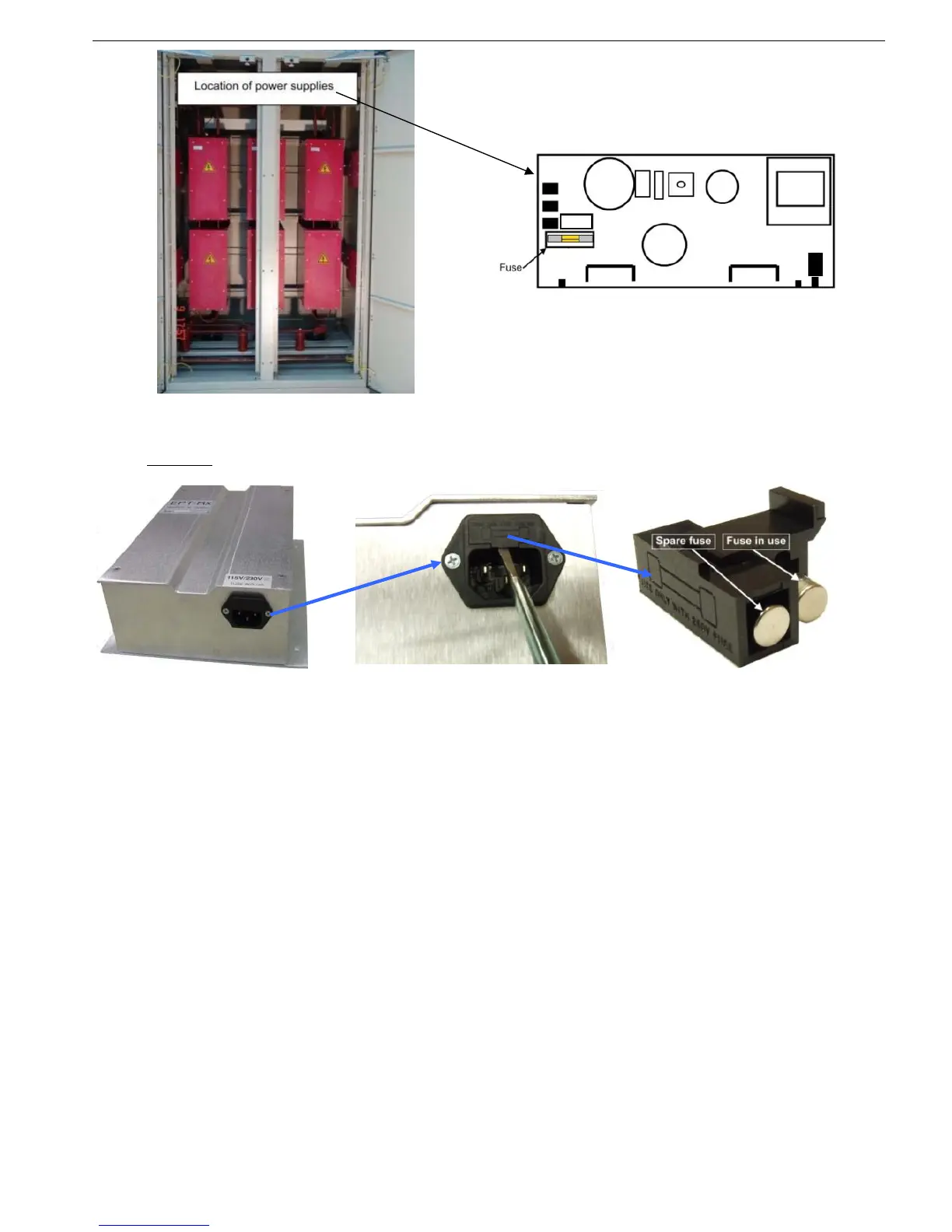
Front View of the Power Section Power Supply to Firing PCB
Figure 36 – Power Supply to Firing PCB (HRVS-DN Models From 10000V and up)
One fuse
is located in the Low voltage compartment, inside the input connector of the Electronic
Potential Transformer Receiver (EPT-Rx). The EPT-Rx is located behind the Control Module.
Bottom view of the EPT-Rx Use 5mm screw driver to remove
the fuse holder from the socket
Fuse holder with fuse in use
and a spare fuse
Figure 37 – EPT-Rx Fuse Replacement Procedure