150 • HRVS-DN Communication (Profibus protocol)
_____________________________________________________________________________________________
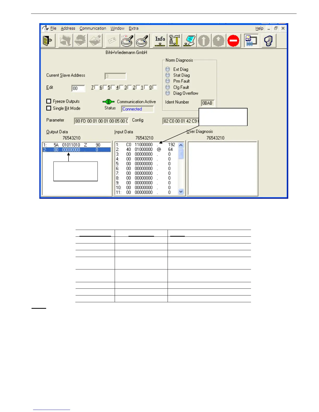
Figure 51 – DPV0 parameters (Cyclic parameters)
17.3.1 Structure of the HRVS-DN Receiving Frame
The first byte must to be 0x5A (90 decimal)
The second byte is as follows:
Bit number: Function: Note:
0 Reserved
1 Reserved
2 Reserved
3 Start/Stop Relay
Write "1" (ON) to Start / Run.
Write "0" (OFF) to Stop.
4 Dual Adjust
Write "1" (ON) to turn On.
Write "0" (OFF) to turn Off.
5 Reserved
6 Reserved
7 Reset Write ‘1’ for reset
Note:
Bit number 0 is the LSB.
Example:
To send Reset, you first need to send 0x5A followed by 0x80.
17.3.2 Structure of the HRVS-DN Transmitting Frame
The return frame contains 20 pairs of bytes (40 bytes total), representing the contents of 20 registers.
Each pair of bytes represents one register; all of the registers are 16 bit numbers.
The first byte represents the high value of the number (the MSB).
17.3.3 Choosing the Receiving DPV0 Registers
There are two methods to change which registers will be displayed in DPV0 (cyclic).
Change the parameters in the GSD file. This method can be used with both DPV0 and DPV1. The change
can only take place when communication is first established.
Receiving from
the HRVS-DN
Sending to the
HRVS-DN