177 • Parameters List
_______________________________________________________________________________________________
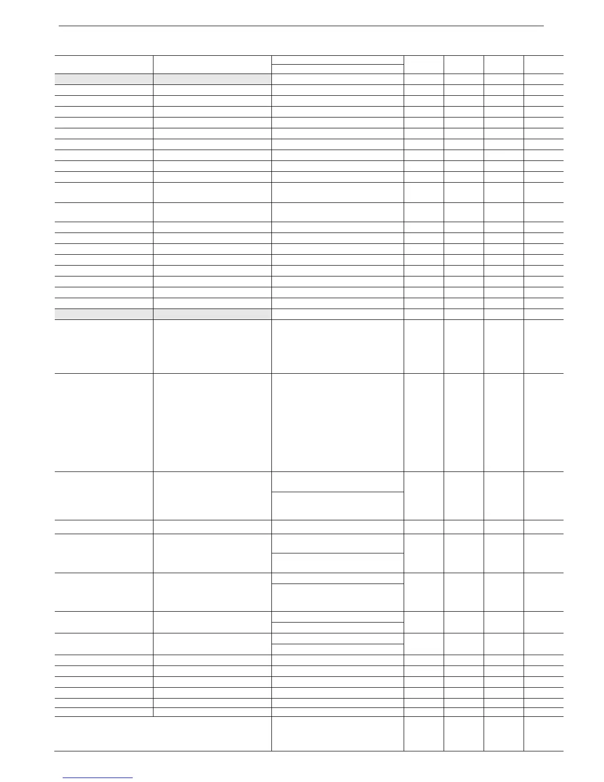
19. PARAMETERS LIST
Parameter Default setting Range Set 1 Set 2 Set 3 Set 4
Range w/dip switch #7=ON
MAIN & PROTECT Refer to section 7.8.2 page 55
RATED LINE VOLT. 6600 VOLT. 2300-15000 VOLT.
STARTER FLC 150 AMP. 20 – 1800 AMP.
MOTOR FLA 150 AMP. 33-100% of STARTER FLC
RATED MOTOR PWR 1000KW 50-40000KW
SERVICE FACTOR 100% 100-130%
UNDERCURR. TRIP 0% OF FLA 0 = OFF, 20-90% of FLA
UNDERCURR. DELAY 10 SEC. 1-40 SEC.
O/C – SHEAR PIN 850% OF FLA 100 – 850% OF FLA
O/C DELAY 0.5 SEC. 0.0 - 5 SEC.
OVERLOAD CLASS IEC CLASS 10 IEC CLASS 5, 10, 15, 20, 25, 30
NEMA CLASS 5, 10, 15, 20, 25, 30
OVERLOAD PROTECT ENABLE WHILE RUN DISABLE, ENABLE WHILE RUN,
ENABLE
UNBALANCE TRIP 20% OF FLA OFF/10-100% OF FLA
UNBALANCE DELAY 5 SEC. 1-60 SEC.
GND FAULT TRIP 20% OF FLA OFF/ 10-100%
GND FAULT DELAY 5 SEC. 1-60 SEC.
UNDERVOLT. TRIP 70% OF Vn 50-90% OF Vn.
UNDERVOLT. DELAY 5 SEC. 1-10 SEC.
OVERVOLT TRIP 120% OF Vn. 110-125% OF Vn
OVERVOLT DELAY 2 SEC. 1-10 SEC.
START PARAMETERS Refer to section 7.8.3 page 60
SOFT START CURVE 1 (STANDARD)
0 (BASIC)= Basic
1 (STANDARD)= Standard Curve
2!! = Pump Control Curve # 1
3!! = Pump Control Curve # 2
4!! = Pump Control Curve # 3
5 (RORQUE) = Torque Control
START TACHO. GAIN
When setting Dip sw. # 2
On for Tacho Mode
Note: Tacho Feedback
functions in its basic form.
Additional curves except
for the basic Linear curve
are optional. Consult the
factory for correct tacho
selection and mechanical
installation.
0 (MIN. GAIN) 0 (MIN. GAIN)= Minimum gain tacho
control
1!! = Second level Tacho gain
2!! = Third level Tacho gain
3!! = Fourth level Tacho gain
4!! = Fifth level Tacho gain
5!! = Sixth level Tacho gain
PULSE LEVEL 70% OF FLA 70-700% OF FLA.
If PULSE TIME>1sec 400%
70-700% OF FLA. If PULSE
TIME>1sec, with the maximum
limitation of: 440x(FLC/FLA)
PULSE TIME 0.0 SEC. 0-10 SEC.
INITIAL VOLTAGE
or INITIAL CURRENT
30%
or 100%
10-50% of Vn
or 100-400% of motor FLA
5-80% of Vn
or 100-400% of motor FLA
CURRENT LIMIT 400% OF FLA 100-400% of motor FLA.
100-700% of motor FLA. With the
maximum limitation of:
440x(FLC/FLA)
ACC. TIME 10 SEC. 1-30 SEC.
1-90 SEC.
MAX. START TIME 30 SEC. 1-30 SEC.
1-250 SEC.
NUMBER OF STARTS 1 1-10, OFF.
STARTS PERIOD 20 MIN. 1-60 MIN.
START INHIBIT 15 MIN. 1-60 MIN.
RUN CONTACT DLY 5 SEC. 0-120 SEC.
TURN BYPASS ON AT * 120% OF FLA 120-300% OF FLA
MIN TIME TO BYPS * 3 SEC. 3-60 SEC.
* Only displays if optional relay PCB is installed and pressing
key for 10 seconds when RUN CONTACT DLY parameters
reaches maximum.