23 • Technical Data
_______________________________________________________________________________________________
4.6 Power Connections Description
Refer to Figure 12 below
Indication Description Remarks
L1, L2, L3 Connection to mains voltage up to
15,000V
Thyristor’s PIV rating, internal circuitry and insulation
defines the following voltage levels:
2,300V +10%/ -15% 50/60Hz
4,160V +10% /-15% 50/60Hz
6,000V +10% /-15% 50/60Hz
6,600V +10% /-15% 50/60Hz
10,000V +10% / -15% 50/60Hz
11,000V +10% / -15% 50/60Hz
13,200V +10% / -15% 50/60Hz
13,800V +10% / -15% 50/60Hz
15,000V +10% / -15% 50/60Hz
Each HRVS-DN is suitable for one of the above
levels & for 50/60 Hz.
L1b, L2b, L3b
(models up to
6.6kV only)
Preparation for bypass
connection
Bypass preparation is standard in all HRVS-DN
models up to 6.6kV.
All HRVS-DN models must be operated with a
Bypass Contactor.
Bus bars and Bypass Contactor must be arranged to
maintain current flow through the internal CTs after
end of the acceleration process. Otherwise, current
protection of the soft starter will not function.
U, V, W Connection to motor
Note:
Never connect power factor capacitors to soft starter
output.
Power Factor capacitors, if required should be
connected to the HRVS-DN line side (mains).
G Connection to ground For proper operation and for safety reasons the
HRVS-DN Power Section must be properly
grounded.
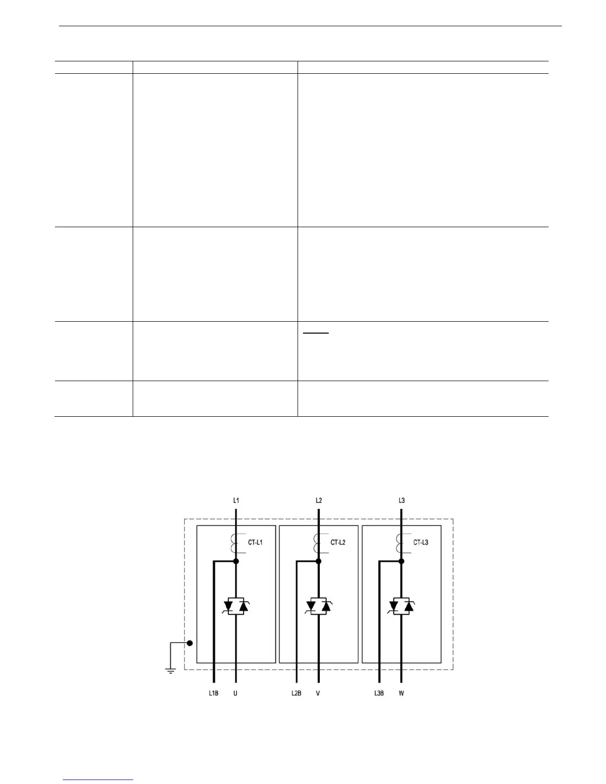
Figure 12 illustrates the Power Section of HRVS-DN models up to 6.6kV.
HRVS-DN models from 10kV and up have no preparation for bypass (bypass must be performed in the
cabinet), CTs are mounted externally to the Power Section and power supplies to the firing PCBs are mounted
externally to the Power Section.
Figure 12 – HRVS-DN up to 6.6kV Power Section