92 • Commissioning and Operation Manual
_____________________________________________________________________________________________
View with medium voltage doors open and customer terminals compartment doors open:
Customer terminals are located in a dedicated compartments on the top of the cabinet.
Line Contactor is mounted on the left medium voltage compartment.
The EPT-Tx (Electronic Potential Transformer Transmitter) is mounted on the medium voltage bus
bars downstream the Line Contactor on the input to the Power Section of the HRVS-DN thus
measuring the input voltage to the Power Section.
The output of the EPT-Tx are two fiber optic wires running to the EPT-Rx (Electronic Potential
Transformer Receiver) which is located in the low voltage compartment.
The harness runs out of the Power Section to the low voltage compartment. This harness includes
both fiber optic wires and copper wires.
The main unit is the Power Section of the soft starter.
Note that this Power Section is actually composed of three identical modules, one per phase.
The input bus bars to the Power Section are on top of it marked L1,L2, L3.
The output bus bars from the Power Section are on its bottom and are marked U, V, W.
Bypass Contactor is mounted on the right medium voltage compartment.
Verify on cabinet label that both, medium voltage and control voltage, are according to the supplied
mains voltage and control voltage.
Input bus bars and output bus bars are located at the bottom of the cabinet.
The input bus bars are at the input cabinet.
The output bus bars are at the output cabinet.
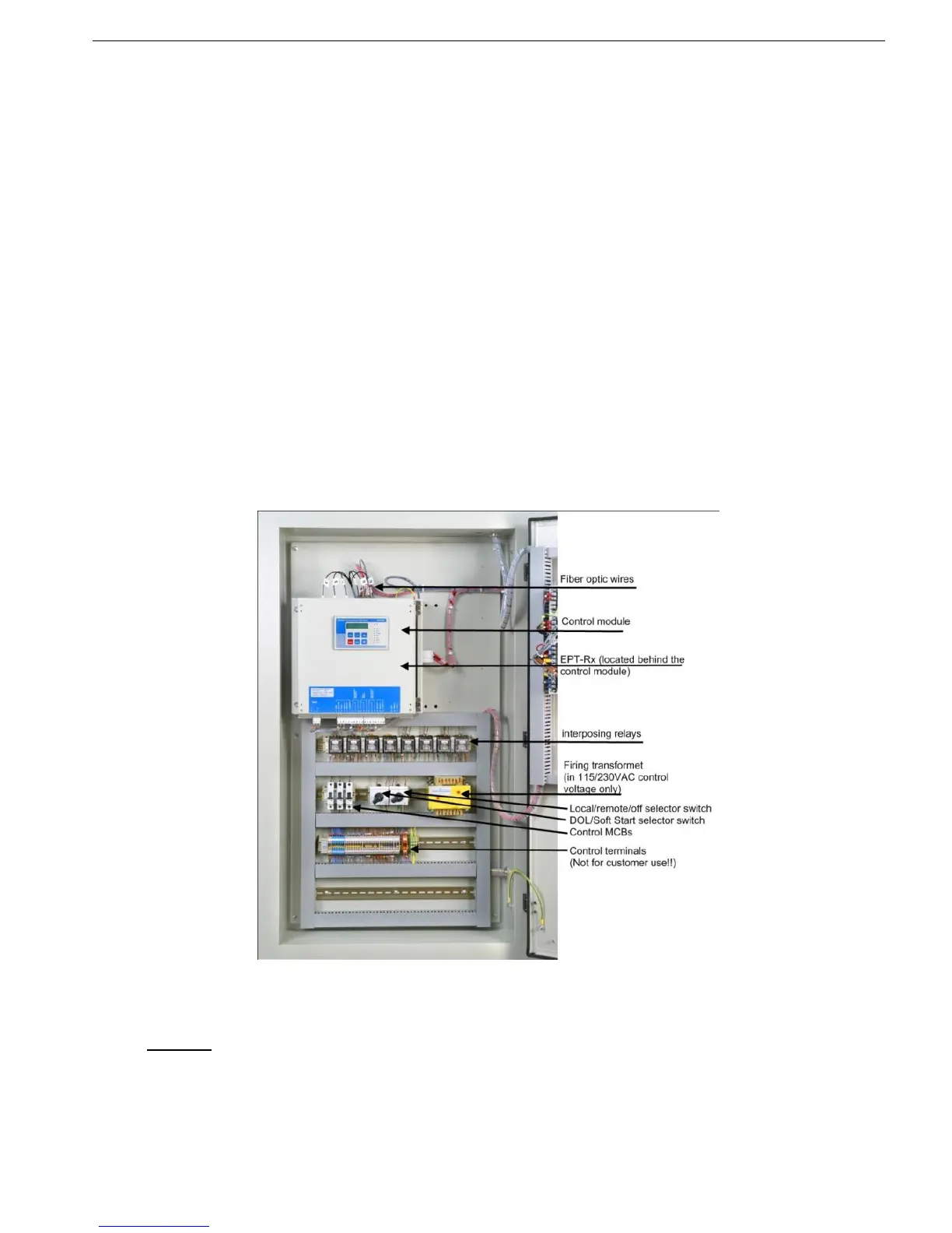
10.2.3 Low Voltage Compartment
Figure 34 - HRVS-DN Low Voltage Compartment
The Control Module is the heart of the soft starter which controls the firing angle of the thyristors
(located in the Power Section).
Warning
: The six fiber optic wires on top of the control unit are sensitive to bending and heat.
The EPT-Rx (Electronic Potential Transformer Receiver) is located behind the Control Module.
Note the two fiber optic wires connecting the EPT-Rx to the EPT-Tx (Electronic Potential Transformer
Transmitter) (located in the Power Section). The EPT-Rx is equipped with a fused supply voltage
connector.
The EPT-Rx provides three phase replica of the mains voltages in level of 120VAC (line to line).
These voltages are connected to the Control Module, and also (optional) to the motor protection relay
(MPR) located on the door of the low voltage compartment.