119
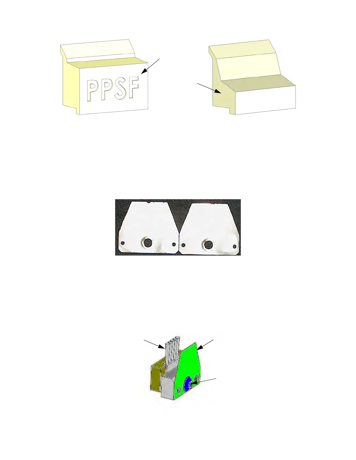
Figure 6-5: Purge Ledge Assemblies
7. Inspect the flicker/brush assemblies.
8
. The top edge of the flicker should be straight. Replace the flicker if it is notched or bent - a small
a
mount of wear is acceptable (Figure 6-6). The flicker can be replaced individually if the brush is
acceptable for reuse.
Figure 6-6: In
specting the Flickers
• The brush bristles must not show evidence of wear from the tip - no notches in the bristle pattern.
•
Frayed bristles are acceptable as long as the top edge is even across all of the bristles.
•
Replace the flicker/brush assembly if the brush does not meet inspection requirements.
9
. Install the flicker/brush assemblies by placing them over the locating pins.
1
0. Install the purge ledge assembly by placing it over the locating pins.
Fi
gure 6-7: Ti
p Wipe Assembly
For PPSF and
ULTEM Material
Standard
Purge Ledge
Only
Acceptable - some
wear is allowed.
Unacceptable
Flicker
Remove Screw
Brush