22
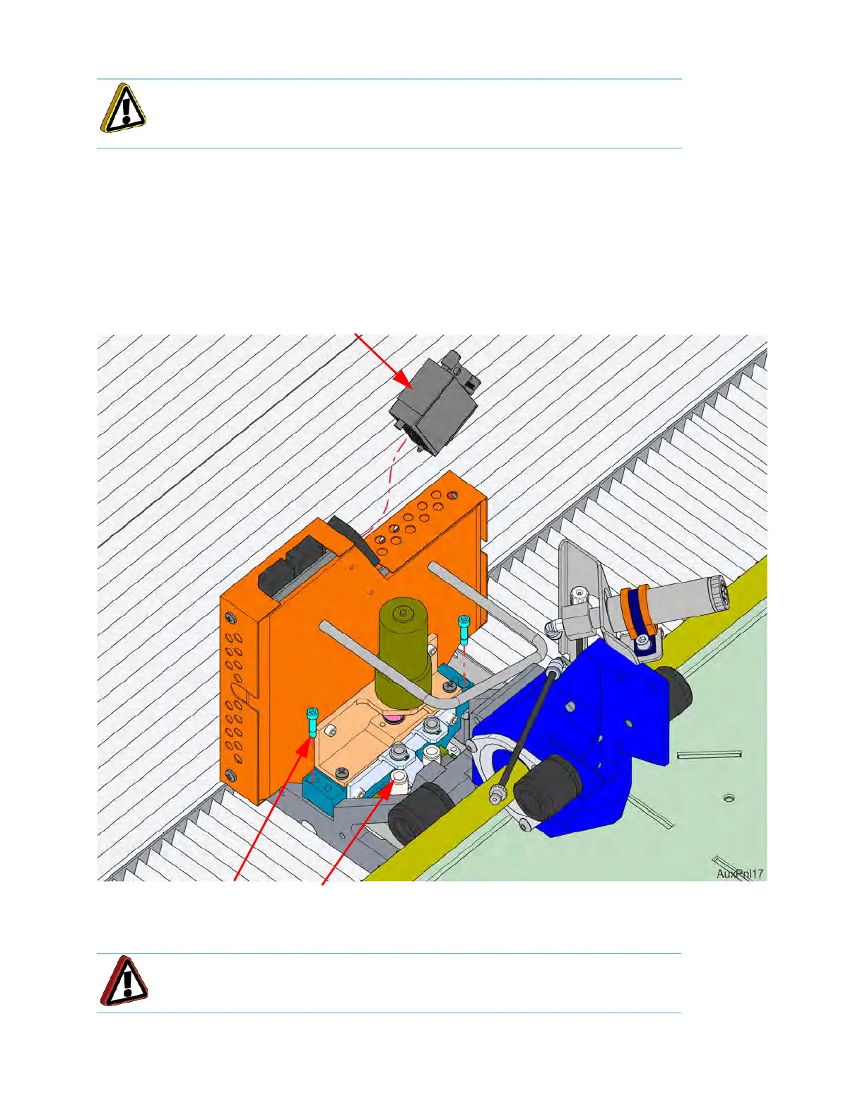
5. Loosen the DECB cable connector thumb screws (2) and disconnect the DECB cable. See Figure 2-11.
6. Using a
9
⁄
64
” allen wrench, completely loosen the head mounting screws (2). See Figure 2-11.
7. Lift the head assembly and place it into the service bracket.
8
. Disconnect the material tubes by pressing down on the lock ring and pulling the tubes upward, out of the
f
itting. See Figure 2-11.
Figure 2-11: He
ad Assembly Components
9. Remove the head assembly from the printer.
Caution: Loosen screws evenly to prevent damage to the connector.
Warning: Head components may still be hot. Use caution when handling.
Head mounting screws (2)
Material Tube
Lock Rings (2)
DECB Cable
Connector