23
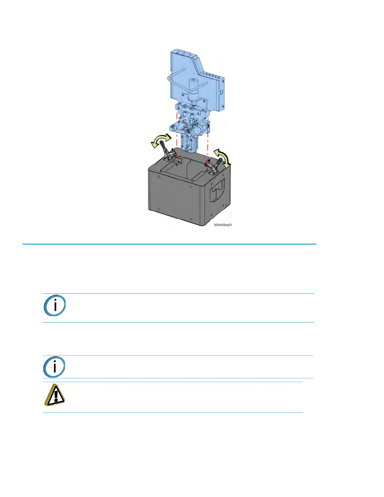
10. Place the head assembly into the docking container and clamp it in place.
Figure 1: Doc
king container detail
11. Move the head and docking container to a secure storage location.
Installing the Nylon CF/Nylon 12CF/ Antero Head
1. Place the Nylon CF head into the service bracket.
2. Connect the model and support material tubes by pushing down into the appropriate lock rings.
S
ee Figure 2-11.
3. Place the head into the mounting plate and use a
9
⁄
64
” allen wrench to reinstall the mounting
screws (2).
4. Connect the DECB cable and hand-tighten the connector thumb screws (2).
5
. Slide the top cover to the closed position.
6
. Power on the printer.
7
. Load material.
8
. Perform the XYZ tip offset calibration.
Note: Be sure to reconnect the model and support tubes in their correct
locations, with the tube labeled “M” to the left and the tube labeled “S” to the
right. Material tubes should be routed in front of the handle on the head.
Note: The DECB cable connector can only be installed one way.
Caution: Tighten screws evenly to prevent damage to the connector.