1D-76 Engine Mechanical:
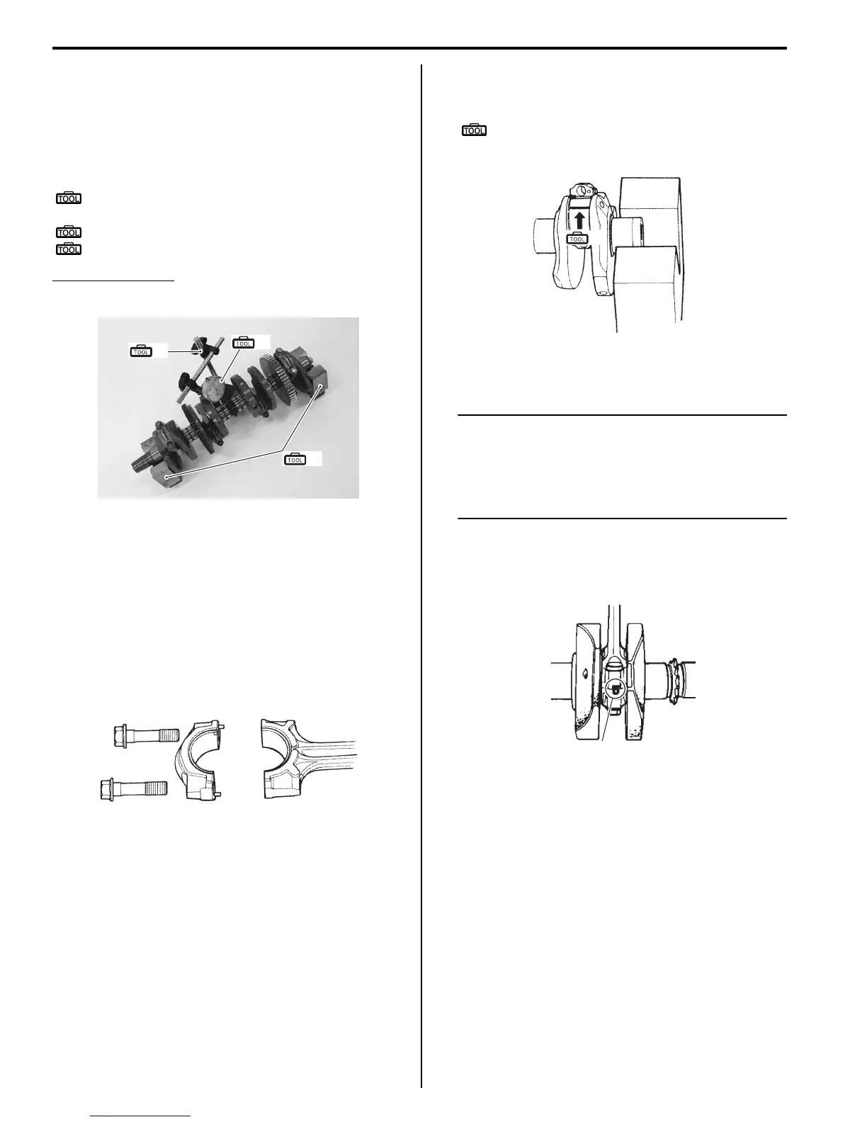
Crankshaft Runout
Support the crankshaft using V-blocks as shown, with
the two end journals resting on the blocks. Set up the
dial gauge as shown, and rotate the crankshaft slowly to
read the runout. Replace the crankshaft if the runout
exceeds the service limit.
Special tool
(A): 09900–20607 (Dial gauge (1/100 mm, 10
mm))
(B): 09900–20701 (Magnetic stand)
(C): 09900–21304 (V-block (100 mm))
Crankshaft runout
Service limit: 0.05 mm (0.002 in)
Conrod Crank Pin Bearing Inspection and
Selection
B718H11406028
Refer to “Conrod Removal and Installation (Page 1D-
74)”.
Inspection
1) Inspect the bearing surfaces for any signs of fusion,
pitting, burn or flaws. If any, replace them with a
specified set of bearings.
2) Place the plastigauge axially along the crank pin,
avoiding the oil hole, as shown.
Special tool
(A): 09900–22301 (Plastigauge (0.025 -
0.076 mm))
3) Tighten the conrod cap bolts to the specified torque,
in two stages.
NOTE
• When installing the conrod cap to the
crank pin, make sure that I.D code “A” on
the conrod faces towards the intake side.
• Never rotate the crankshaft or conrod
when a piece of plastigauge is installed.
Tightening torque
Conrod cap bolt: 21 N⋅m (2.1 kgf-m, 15.0 Ib-ft)
then turn in 1/4 (90°) turn.
(A)
(C)
(B)
I718H1140283-01
I718H1140285-01
(A)
I718H1140286-01
“A”
I718H1140287-01

 Loading...


