1D-72 Engine Mechanical:
• Install the spacer (7).
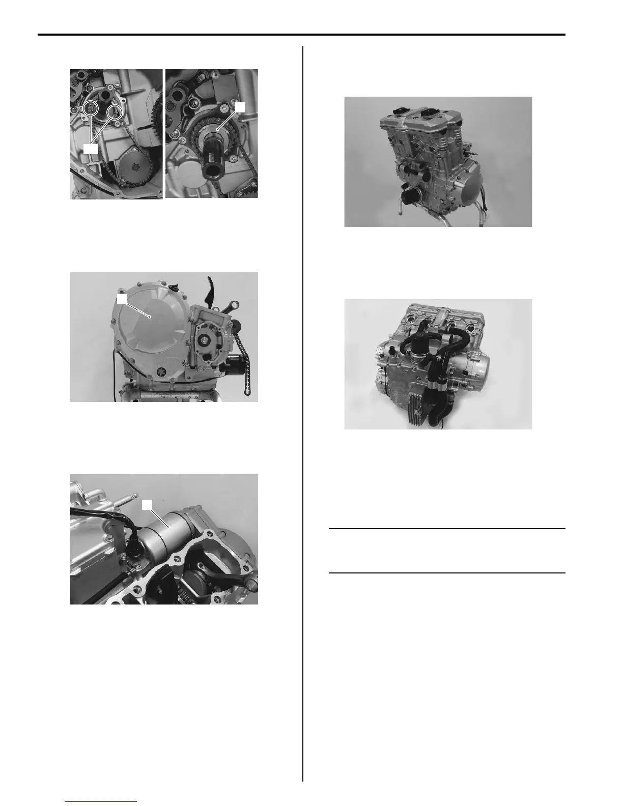
Clutch
• Install the clutch component parts (1). Refer to “Clutch
Installation in Section 5C (Page 5C-14)”.
Starter Motor
• Install the starter motor (1). Refer to “Starter Motor
Removal and Installation in Section 1I (Page 1I-4)”.
Engine Top Side
• Assemble the engine top side. Refer to “Engine Top
Side Assembly (Page 1D-28)”.
Water Hose
• Connect the water hoses. Refer to “Water Hose
Routing Diagram in Section 1F (Page 1F-3)”.
Crank Balancer Disassembly and Assembly
B718H11406032
Refer to“Engine Bottom Side Disassembly (Page 1D-
53)”.
Refer to “Engine Bottom Side Assembly (Page 1D-61)”.
NOTE
It is unnecessary to remove the engine
assembly from the frame when removing the
crank balancer.
7
“C”
I718H1140255-01
1
I718H1140256-01
1
I718H1140257-01
I718H1140258-01
I718H1140259-01

 Loading...


