Manual Transmission: 5B-15
Gearshift Construction
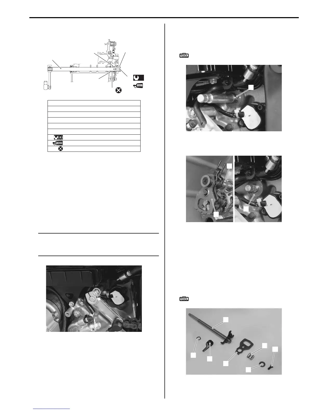
B718H15206015
Gearshift Shaft / Gearshift Cam Plate Removal
and Installation
B718H15206011
Removal
1) Remove the engine sprocket outer cover. Refer to
“Engine Sprocket Removal and Installation in
Section 3A (Page 3A-2)”.
2) Disengage the gearshift link arm by removing the
bolt.
NOTE
Mark the gearshift shaft head at which the
gearshift link arm slit set for correct
reinstallation.
3) Remove the clutch components. Refer to “Clutch
Removal in Section 5C (Page 5C-13)”.
4) Remove the snap ring (1) from the gearshift shaft.
Special tool
: 09900–06107 (Snap ring pliers)
5) Remove the gearshift shaft assembly (2) and
washers (3).
6) Remove the following parts from the gearshift shaft
(4).
• Snap ring (5)
• Gearshift return spring (6)
• Gearshift cam drive plate (7)
• Plate return spring (8)
• Washer (9)
• End bolt (10)
Special tool
: 09900–06107 (Snap ring pliers)
1. Gearshift shaft
2. Washer
3. Snap ring
4. Gearshift shaft return spring
5. Gearshift plate return spring
6. Gearshift shaft end bolt
: 10 N⋅m (1.0 kgf-m, 7.0 lb-ft)
: Apply thread lock to thread part.
: Do not reuse.
(a)
1
2
3
5
6
4
I718H1520002-02
I718H1520046-01
1
I718H1520047-01
2
3
3
I718H1520048-02
5
6
7
8
4
9
10
I718H1520049-02

 Loading...


