Engine Cooling System: 1F-9
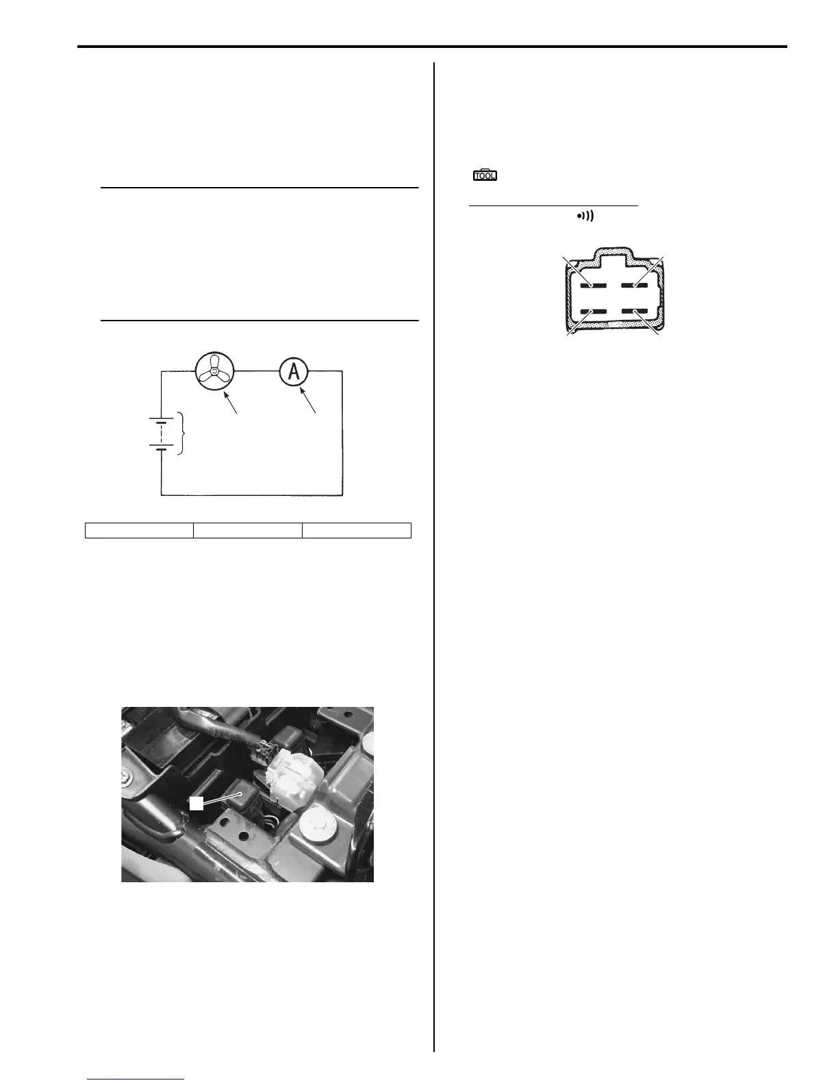
2) Test the cooling fan motor for load current with an
ammeter connected as shown in the figure.
If the fan motor does not turn, replace the cooling fan
assembly with a new one. Refer to “Radiator /
Cooling Fan Motor Removal and Installation
(Page 1F-5)”.
NOTE
• When making this test, it is not necessary
to remove the cooling fan.
• The voltmeter is for making sure that the
battery applies 12 V to the motor. With the
fan motor with electric motor fan running
at full speed, the ammeter should be
indicating not more than 5 A.
3) Connect the cooling fan motor coupler.
Cooling Fan Relay Inspection
B718H11606021
Inspect the fan relay in the following procedures:
1) Remove the seat. Refer to “Exterior Parts Removal
and Installation in Section 9D (Page 9D-6)”.
2) Remove the cooling fan relay (1).
3) First check the insulation between “A” and “B”
terminals with tester. Then apply 12 volts to “C” and
“D” terminals, (+) to “C” and (–) to “D”, and check the
continuity between “A” and “B”.
If there is no continuity, replace it with a new one.
Special tool
: 09900–25008 (Multi-circuit tester set)
Tester knob indication set
Continuity test ( )
4) Reinstall the removed parts.
ECT Sensor Removal and Installation
B718H11606022
Refer to “ECT Sensor Removal and Installation in
Section 1C (Page 1C-2)”.
ECT Sensor Inspection
B718H11606023
Refer to “ECT Sensor Inspection in Section 1C
(Page 1C-3)”.
Thermostat Connector / Thermostat Removal
and Installation
B718H11606024
Removal
1) Drain a small amount of engine coolant. Refer to
“Cooling System Inspection in Section 0B (Page 0B-
12)”.
2) Remove the fuel tank. Refer to “Fuel Tank Removal
and Installation in Section 1G (Page 1G-9)”.
3) Remove the thermostat connector bracket bolts.
4) Disconnect the following parts from the thermostat
connector (1).
• Water bypass hose (2)
• Cylinder outlet left hose (3)
• Cylinder outlet right hose (4)
• Radiator inlet hose (5)
• Reservoir tank inlet hose (6)
2. Fan motor 3. Ammeter 4. Battery
2
3
4
I718H1160048-01
1
I718H1160005-01
“A”
“B”
“C”
“D”
I718H1160006-03

 Loading...


