Starting System: 1I-13
Starter Button Inspection
B718H11906012
Inspect the starter button in the following procedures:
1) Remove the right frame head cover. (GSF1250/A)
Refer to “Exterior Parts Removal and Installation in
Section 9D (Page 9D-6)”.
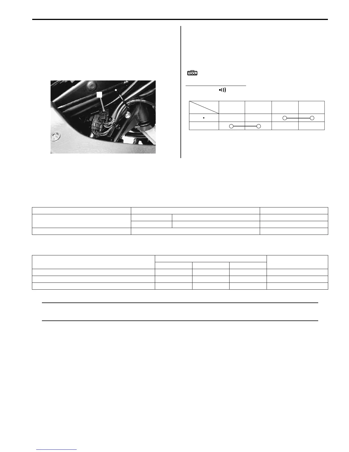
2) Disconnect the right handlebar switch coupler (1).
3) Inspect the starter button for continuity with a tester.
If any abnormality is found, replace the right handle
switch assembly with a new one. Refer to
“Handlebar Removal and Installation in Section 6B
(Page 6B-3)”.
Special tool
: 09900–25008 (Multi-circuit tester set)
Tester knob indication
Continuity ( )
4) After finishing the starter button inspection, reinstall
the removed parts.
Specifications
Service Data
B718H11907001
Unit: mm (in)
Tightening Torque Specifications
B718H11907002
NOTE
The specified tightening torque is also described in the following.
“Starter Motor Components (Page 1I-3)”
Reference:
For the tightening torque of fastener not specified in this section, refer to “Tightening Torque Specifications in Section
0C (Page 0C-7)”.
1
I718H1190037-01
Position
Color
PUSH
B/R Bl/B B/Y
B/W
I718H1190040-01
Item Specification Note
Starter motor brush length
Standard 12.0 (0.47)
Limit 6.5 (0.26)
Starter relay resistance 3 – 6 Ω
Fastening part
Tightening torque
Note
N⋅mkgf-mlb-ft
Starter motor lead wire mounting nut 5 0.5 3.5 )(Page 1I-4)
Starter motor housing bolt 5 0.5 3.5 )(Page 1I-5)
Starter clutch bolt 25 2.5 18.0 )(Page 1I-12)

 Loading...


