9C-1 Combination Meter / Fuel Meter / Horn:
Body and Acc essories
Combination Meter / Fuel Meter / Horn
General Description
Combination Meter System Description
B718H19301001
This combination meter mainly consists of the stepping motor, LCD (Liquid Crystal Display) and LED (Light Emitting
Diode).
The rpm pointer is driven by the stepping motor.
The LCDs indicate Speed, Odo / Trip A / Trip B, Fuel level indicator and Clock / FI (DTC) respectively.
LED (Light Emitting Diode)
LED is used for the illumination light and each indicator light.
LED is maintenance free. LED is less power consuming and more resistant to vibration resistance compared to the
bulb.
FI
1
2 3 5
6
7
9 8
4
1110 12 1314 14
I718H1930048-01
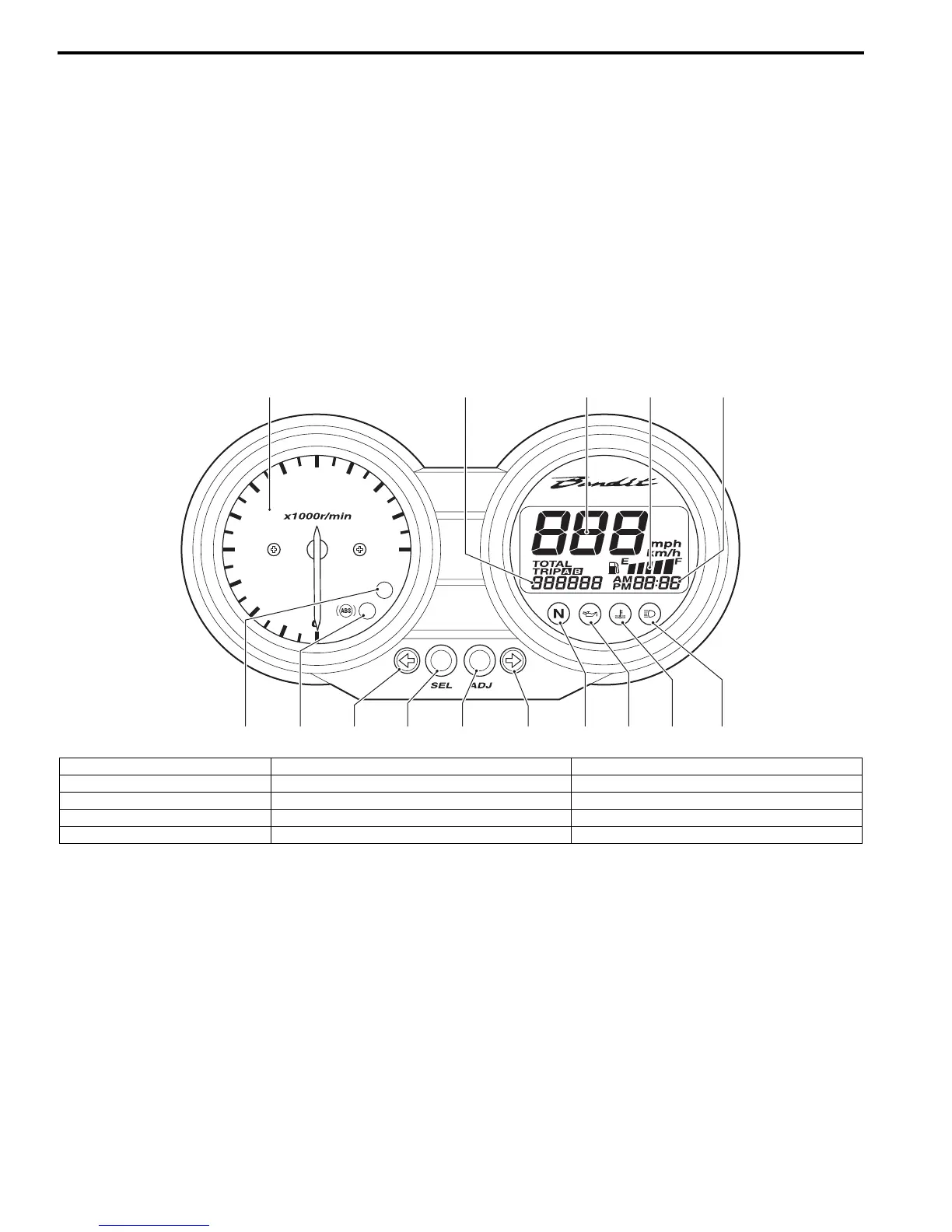
1. Adjust switch (Trip / Clock) 6. Select switch (Odo / Trip A / Trip B) 11. LED (Oil pressure indicator light)
2. Tachometer 7. LCD (FI / Clock) 12. LED (Engine coolant temperature indicator light)
3. LCD (Speedometer) 8. LED (ABS indicator light) [GSF1250A/SA only] 13. LED (High-beam indicator light)
4. LCD (Odo / Trip A / Trip B) 9. LED (FI indicator light) 14. LED (Turn signal indicator light)
5. LCD (Fuel level indicator) 10. LED (Neutral indicator light)

 Loading...


