4A-15 Brake Control System and Diagnosis:
Installation
Install the front brake master cylinder in the reverse
order of removal. Pay attention to the following points:
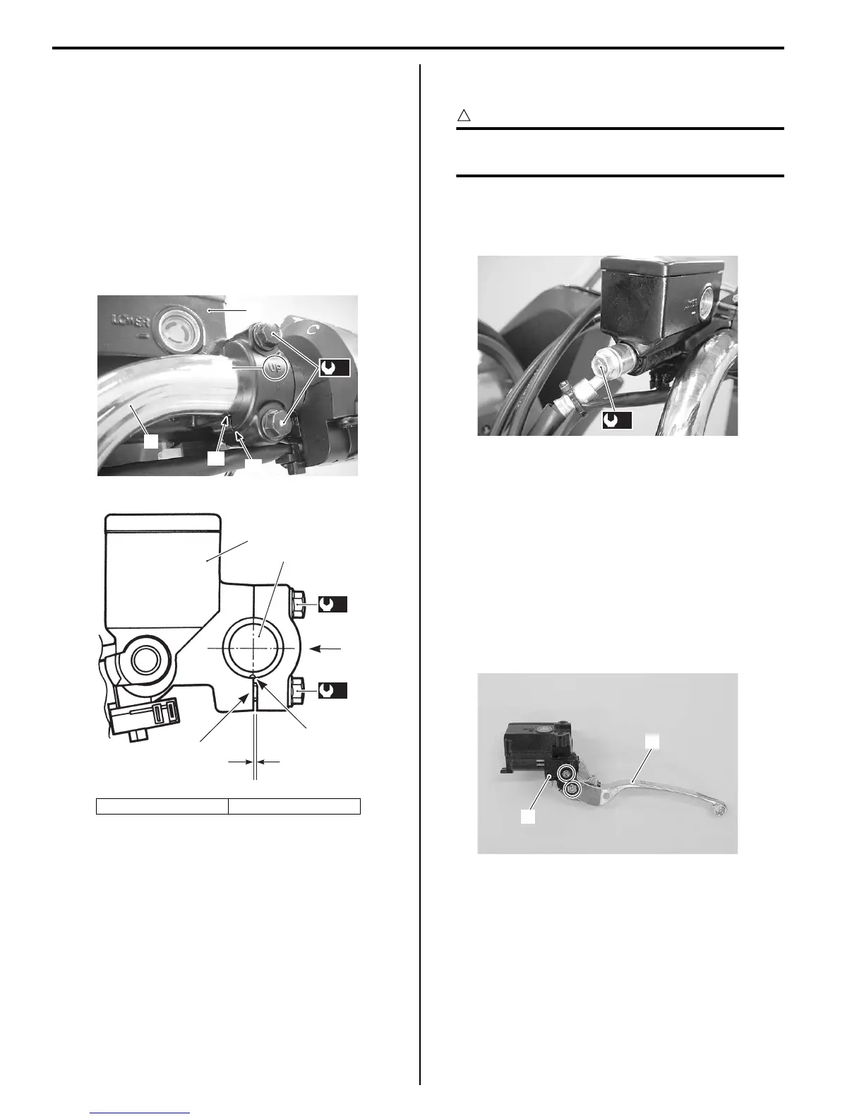
• When installing the master cylinder (1) onto the
handlebars (2), align the master cylinder holder’s
mating surface “A” with the punch mark “B” on the
handlebars (2) and tighten the upper holder bolt first.
Refer to “Handlebar Construction in Section 6B
(Page 6B-2)”.
Tightening torque
Master cylinder holder bolt (Upper and Lower)
(a): 10 N·m (1.0 kgf-m, 7.0 lb-ft)
• After setting the brake hose union to the stopper,
tighten the union bolt to the specified torque.
CAUTION
!
The seal washers should be replaced with the
new ones to prevent fluid leakage.
Tightening torque
Brake hose union bolt (b): 23 N·m (2.3 kgf-m, 16.5
lb-ft)
• Bleed air from the brake system. Refer to “Air
Bleeding from Brake Fluid Circuit (Page 4A-8)”.
Front Brake Master Cylinder / Brake Lever
Disassembly and Assembly
B718H14106013
Refer to “Front Brake Master Cylinder Assembly
Removal and Installation (Page 4A-14)”.
Disassembly
1) Remove the brake lever (1) and brake light switch
(2).
“C”: Up mark “a”: Clearance
(a)
2
“C”
1
“B”
“A”
I718H1410051-04
1
2
“C”
(a)
(a)
“B”
“A”
“a”
I718H1410072-01
(b)
I718H1410050-03
1
2
I718H1410052-01

 Loading...


