9C-7 Combination Meter / Fuel Meter / Horn:
5) Turn the ignition switch ON.
6) Check the display of fuel level indicator (LCD) as
shown.
If any abnormality is found, replace the combination
meter with a new one. Refer to “Combination Meter
Removal and Installation (Page 9C-4)”.
NOTE
It takes approx. 30 seconds that the fuel level
indicator indicates the detected fuel level.
7) Connect the fuel level gauge coupler and reinstall
the fuel tank.
Refer to “Fuel Tank Removal and Installation in
Section 1G (Page 1G-9)”.
Fuel Level Indicator Switch (Thermistor)
Inspection
B718H19306031
Inspect the fuel level indicator switch in the following
procedures:
1) Remove the fuel pump. Refer to “Fuel Pump
Assembly / Fuel Level Gauge Removal and
Installation in Section 1G (Page 1G-11)”.
2) Remove the thermistor from the fuel pump. Refer to
“Fuel Pump Disassembly and Assembly in Section
1G (Page 1G-12)”.
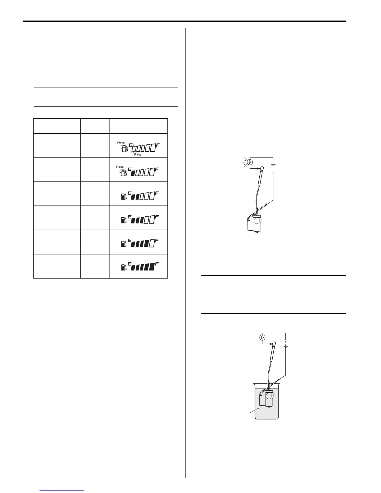
3) Connect 12 V battery and test bulb (12 V, 3.4 W) to
the fuel level indicator switch as shown in the figure.
The bulb should come on after one minutes if the
switch is in good condition.
4) When the switch is immersed in kerosene, the bulb
should go out. If the bulb remains lit, replace the unit
with a new one.
NOTE
• When the bulb turns off, immediately pick
up the switch from kerosene.
• After the check has been completed, wash
the switch with gasoline.
5) Reinstall the removed parts. Refer to “Fuel Pump
Disassembly and Assembly in Section 1G (Page 1G-
12)”.
Resistance Thermistor
—
More than 212 Ω
129 – 212 Ω
76 – 160 Ω
36 – 93 Ω
Less than 36 Ω
Fuel level meter
ON
OFF
OFF
OFF
OFF
OFF
ON
ON
ON
ON
I718H1930060-01
ON
Test
bulb
Battery
I718H1930013-04
Kerosene
OFF
Test
bulb
Battery
I718H1930014-03

 Loading...


