4E-11 ABS:
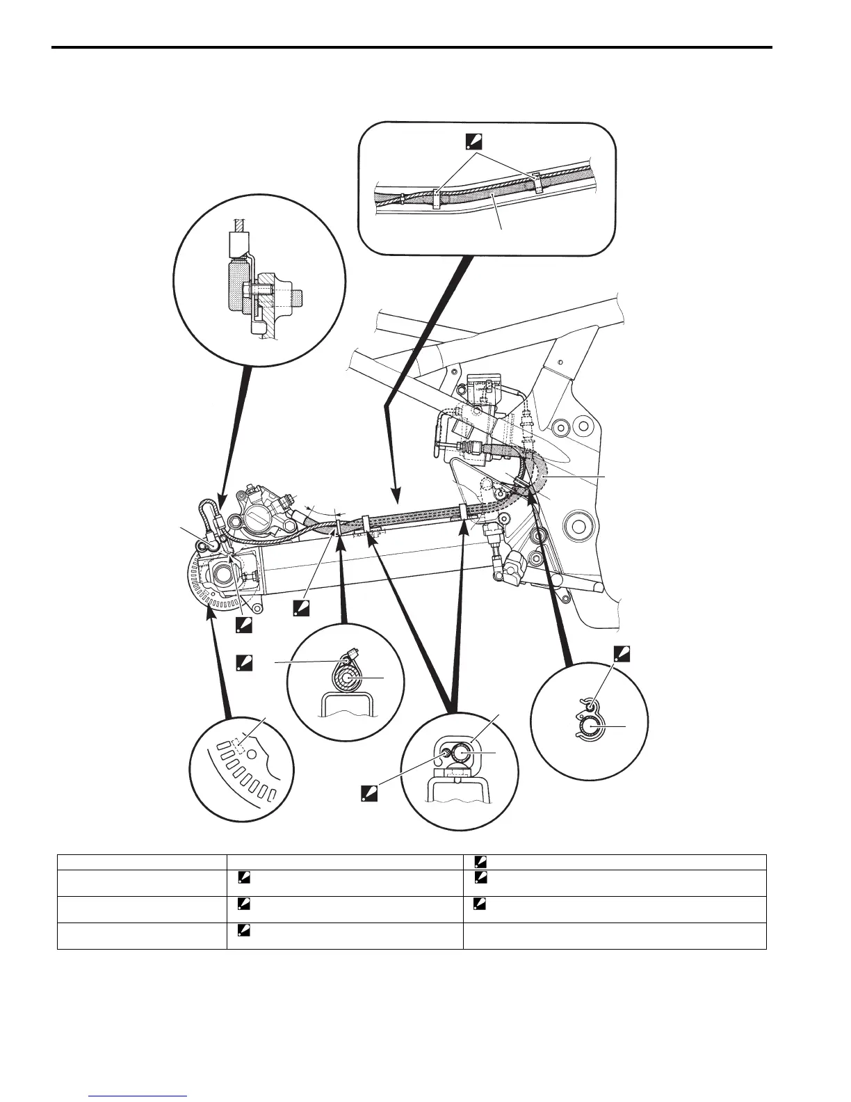
Rear Wheel Speed Sensor Routing Diagram
B718H14502004
1
2
2
2
2
3
“A”
“D”
“E”
“F”
“G”
4
“a”
“C”
“B”
I718H1450118-03
1. Rear wheel speed sensor “A”: Outside mark “E”: Pass through the sensor lead wire on the brake hose.
2. Brake hose No.2 “B”: After the clamp has contacted to the
stopper, tighten the bolt.
“F”: Clamp the sensor lead wire upper side of brake hose.
3. Brake hose No.1 “C”: Clamp sensor lead wire with white tape
matched green paint of brake hose.
“G”: Pass through the sensor lead wire inside of the brake
hose.
4. Brake hose guide “D”: Pass through the sensor lead wire inside
of the brake hose guide.
“a”: 35 mm (1.4 in)

 Loading...


