Engine General Information and Diagnosis: 1A-28
DTC “C13” (P0105-H/L): IAP Sensor (No.1) Circuit Malfunction
B718H11104012
Detected Condition and Possible Cause
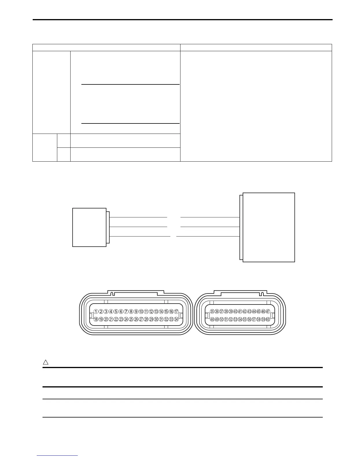
Wiring Diagram
ECM coupler (Harness side)
Troubleshooting
CAUTION
!
When using the multi-circuit tester, do not strongly touch the terminal of the ECM coupler with a
needle pointed tester probe to prevent the terminal damage or terminal bend.
NOTE
After repairing the trouble, clear the DTC using SDS tool. Refer to “Use of SDS Diagnosis Reset
Procedures (Page 1A-13)”.
Detected Condition Possible Cause
C13
IAP sensor (No.1) voltage is not within the
following range.
0.5 V ≤ Sensor voltage < 4.85 V
NOTE
Note that atmospheric pressure
varies depending on weather
conditions as well as altitude.
Take that into consideration
when inspecting voltage.
• Clogged vacuum passage between throttle body and
IAP sensor (No.1).
• Air being drawn from vacuum passage between throttle
body and IAP sensor (No.1).
• IAP sensor (No.1) circuit open or shorted to the ground.
• IAP sensor (No.1) malfunction.
• ECM malfunction.
P0105
H
Sensor voltage is higher than specified
value.
• IAP sensor (No.1) circuit is open or shorted to Vcc or
ground circuit open.
L
Sensor voltage is lower than specified
value.
• IAP sensor (No.1) circuit is shorted to the ground or Vcc
circuit open.
B/Br
W/Bl
B
ECM
Vcc
E2
IAP sensor (No.1)
IAP (No.1)
26
29
11
I718H1110017-08
I718H1110240-01

 Loading...


