Charging System: 1J-1
Engine
Charging System
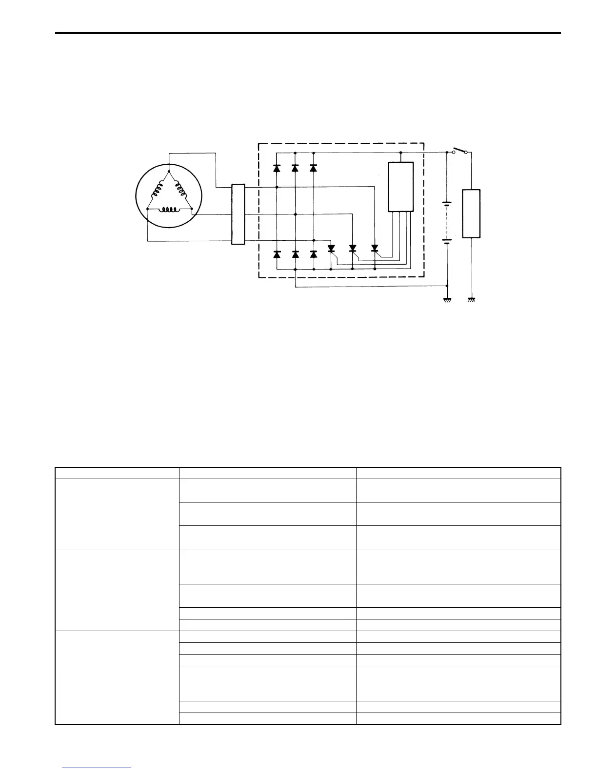
Schematic and Routing Diagram
Charging System Diagram
B718H11A02001
Component Location
Charging System Components Location
B718H11A03001
Refer to “Electrical Components Location in Section 0A (Page 0A-8)”.
Diagnostic Information and Procedures
Charging System Symptom Diagnosis
B718H11A04001
SCR
IC
Generator
Regulator/Rectifier
Ignition switch
Battery
Load
I718H11A0001-01
Condition Possible cause Correction / Reference Item
Generator does not
charge
Open- or short-circuited lead wires, or
loose lead connections.
Repair, replace or connect properly.
Short-circuited, grounded or open
generator coil.
Replace.
Short-circuited or punctured regulator/
rectifier.
Replace.
Generator does charge,
but charging rate is below
the specification
Lead wires tend to get short- or open-
circuited or loosely connected at
terminals.
Repair or retighten.
Grounded or open-circuited generator
coil.
Replace.
Defective regulator/rectifier. Replace.
Defective cell plates in the battery. Replace the battery.
Generator overcharges Internal short-circuit in the battery. Replace the battery.
Damaged or defective regulator/rectifier. Replace.
Poorly grounded regulator/rectifier. Clean and tighten ground connection.
Unstable charging Lead wire insulation frayed due to
vibration, resulting in intermittent short-
circuiting.
Repair or replace.
Internally short-circuited generator. Replace.
Defective regulator/rectifier. Replace.

 Loading...


