1G-3 Fuel System:
Schematic and Routing Diagram
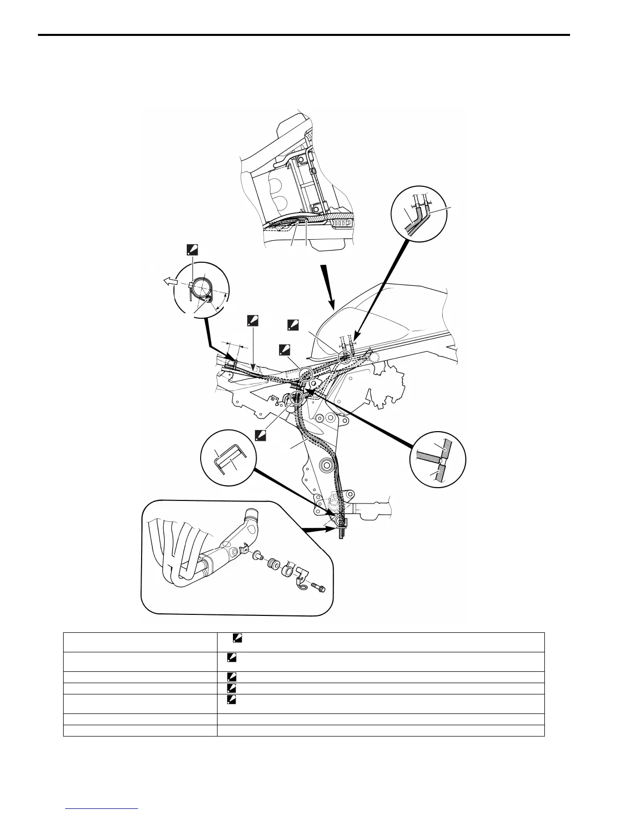
Fuel Tank Drain Hose and Breather Hose Routing Diagram
B718H11702002
1
2
1 2
“a”
4
In
sid
e
8
“b”
“C”
6
7
3
“B”
“D”
“A”
5
1
I718H1170040-02
1. Fuel tank drain hose 8. Clamp
: Clamp end should face inside. Tip of clamp should face downward.
2. Fuel tank breather hose No.1 “A”: Be careful not to bind the fuel tank drain hose and fuel tank breather hose with the other
hoses and wire harness.
3. Fuel tank breather hose No.2 “B”: Pass the breather hose and drain hose through outside the reservoir tank inlet hose.
4. Fuel tank breather hose No.3 “C”: Be careful for the hose not to be slackened.
5. Fuel tank drain hose No.2 “D”: Pass the breather hose and drain hose through outside the brake pipe.
Pass the breather hose and drain hose through ahead of connector.
6. Frame “a”: 45° ± 15°
7. Drain hose guide “b”: 30 ± 10 mm (1.2 ± 0.4 in)

 Loading...


