2B-3 Front Suspension:
2) Tighten the front fork cap bolt (2) to the specified
torque with the special tool.
Tightening torque
Front fork cap bolt (a): 23 N·m (2.3 kgf-m, 16.5
lb-ft)
3) Loosen the lower clamp bolts.
4) Set the front fork with the upper surface “T” of the
inner tube positioned 1.8 mm (0.071 in) “a” from the
upper surface of the upper bracket.
5) Tighten the front fork lower clamp bolts (1).
Tightening torque
Front fork lower clamp bolt (b): 23 N·m (2.3 kgf-
m, 16.5 lb-ft)
6) Tighten the front fork upper fork clamp bolt (3).
Tightening torque
Front fork upper clamp bolt (c): 23 N·m (2.3 kgf-
m, 16.5 lb-ft)
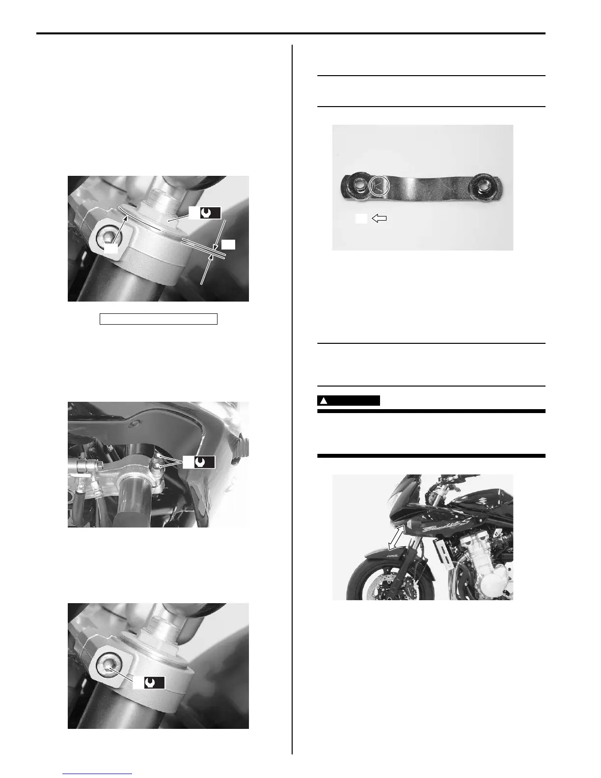
7) Set the front fender plate nut to the front fender.
NOTE
Face the triangle mark on the front fender
brace to the front side “A”.
8) Remount the front fender along with the fender plate
nut.
9) Install the front wheel assembly. Refer to “Front
Wheel Assembly Removal and Installation in Section
2D (Page 2D-6)”.
NOTE
Before tightening the front axle and front axle
pinch bolts, move the front fork up and down
four or five times.
WARNING
!
After remounting the brake caliper, pump the
brake lever until the pistons push the pads
correctly.
Front Fork Inspection
B718H12206004
Refer to “Front Fork Inspection in Section 0B (Page 0B-
20)”.
“a”: 1.8 mm (0.71 in))
“T”
(a)
2
“a”
I718H1220007-06
(b)
1
I718H1220008-05
(c)
3
I718H1220009-03
“A”
I718H1220010-02
I718H1240014-02

 Loading...


