4A-5 Brake Control System and Diagnosis:
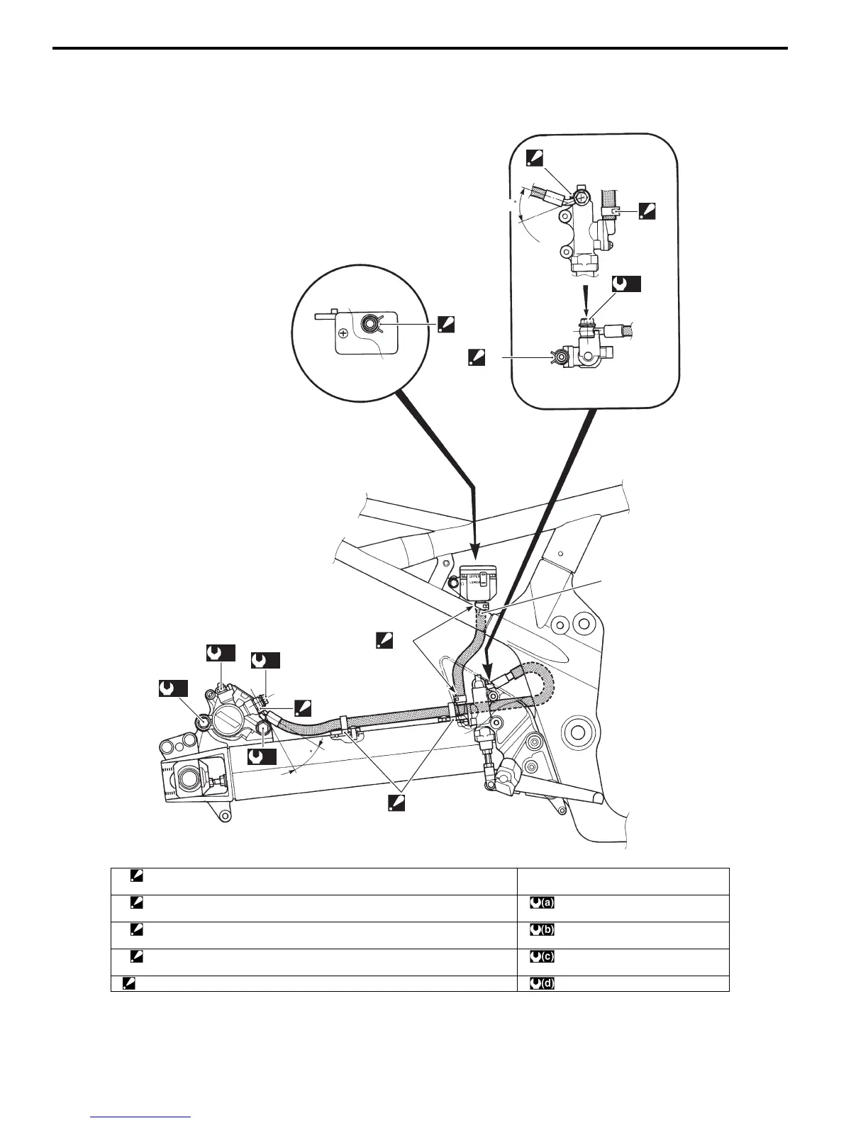
Rear Brake Hose Routing Diagram
B718H14102002
GSF1250/S
(b)
(a)
(c)
(d)
28
3
4
“B”
1
42
3
2
(a)
2
“A”
I718H1410062-03
1. Brake hose clamp
: Brake hose clamp ends should face forward.
“B”: White paint
2. Brake hose clamp
: Brake hose clamp ends should face backward.
: 23 N⋅m (2.3 kgf-m, 16.5 lb-ft)
3: Stopper
: After the brake hose union has contacted the stopper, tighten the union bolt.
:6 N⋅m (0.6 kgf-m, 4.5 lb-ft)
4: Guide
: Position the guide with hole of swingarm before tightening.
: 22 N⋅m (2.2 kgf-m, 16.0 lb-ft)
“A”: Insert the brake hose firmly. : 27 N⋅m (2.7 kgf-m, 19.5 lb-ft)

 Loading...


