Clutch: 5C-2
Schematic and Routing Diagram
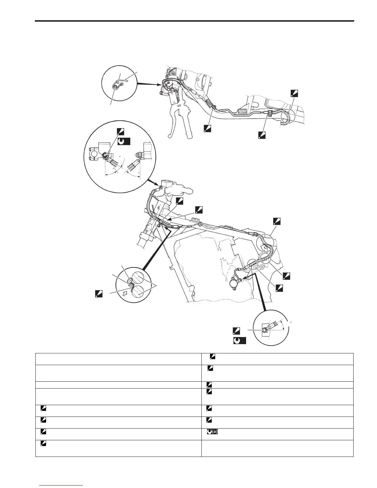
Clutch Hose Routing Diagram
B718H15302001
1
3
2
5
6
7
8
(a)
35
21
49
4
1
2
10
9
“A”
“B”
“C”
“D”
8
(a)
30
I718H1530005-05
1. Wiring harness 9. Clutch hose No.3 clamp
: After positioning the clamp with stopper, tighten the bolt.
2. Clutch hose 10. Grommet
: Install the grommet of the clutch hose to the clutch hose guide
properly.
3. Guide (GSF1250S/SA only) “A”: Pass the wiring harness through upper the clutch hose No.3 clamp.
4. Frame “B”: Clutch hose
: Pass through the clutch hose between the frame and fuel tank rail.
Be careful not to contact the clutch hose and frame cover bracket.
5. Clutch hose clamp
: Insert the clutch hose clamp end to the hole of the frame fully.
“C”: pass the clutch hose through outside of the frame.
6. Clutch hose No.2 clamp
: After positioning the clamp with stopper, tighten the bolt.
“D”: Pass the clutch hose through outside of the wiring harness.
7. Clutch hose
: Pass through the clutch hose under the frame.
:23 N⋅m (2.3 kgf-m, 16.5 lb-ft)
8. Union bolt
: After the clutch hose union has contacted the stopper, tighten the union
bolt.

 Loading...


