CHAPTER 3 Design and Function
Sysmex XE-5000 Instructions for Use 3-3
Revised April 2007 EU
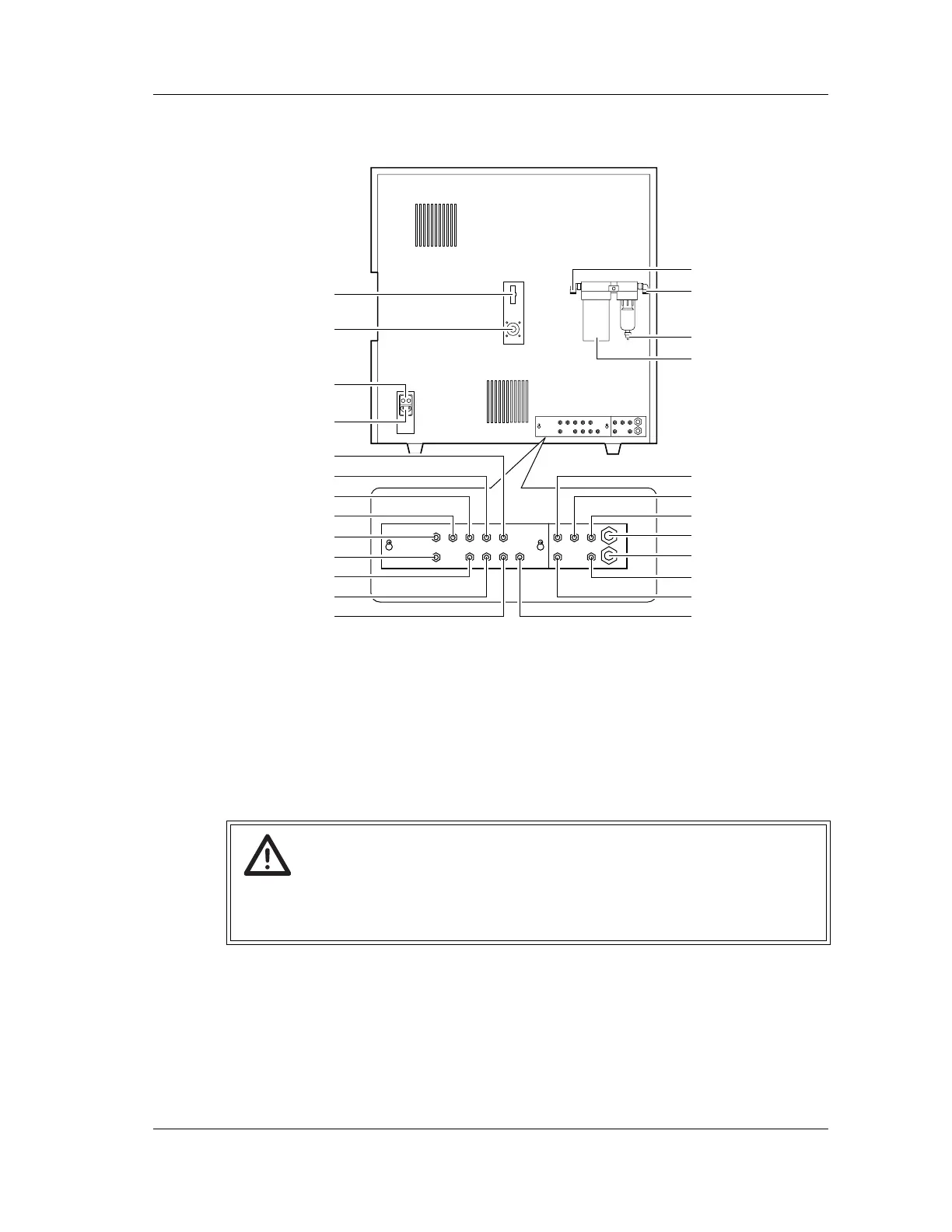
Rear View
1 Float switch connector
Connected to the float switch of each reagent.
2 Pneumatic Unit control output connector
Used as output connector for controlling ON/OFF of the Pneumatic Unit power.
Connected to the connector on the rear panel of the Pneumatic Unit.
3 Fuse holder
This is a 250V, 3.15A (time lag) fuse.
4 AC power supply
Supplies power using the provided power cable.
5 ESE inlet nipple (ESE-1)
CELLSHEATH is aspirated via this nipple. Connected to the lower nipple of the
CELLSHEATH float switch.
Warning!
• To avoid electrical shock, disconnect supply before servicing.
• For the continued protection against risk of fire, replace only with a fuse of the
specified type and current ratings.
9
2
1
4
3
8
11
10
12
13 25
24
23
22
21
20
19
18
17
16
15
14
7
6
5