Nonmaskable Interrupts
3-20
ÁÁÁÁÁÁÁÁÁÁÁÁÁÁÁÁÁÁÁÁÁÁÁÁÁÁÁÁÁÁ
ÁÁÁÁÁÁÁÁÁÁÁÁÁÁÁÁÁÁÁÁÁÁÁÁÁÁÁÁÁÁ
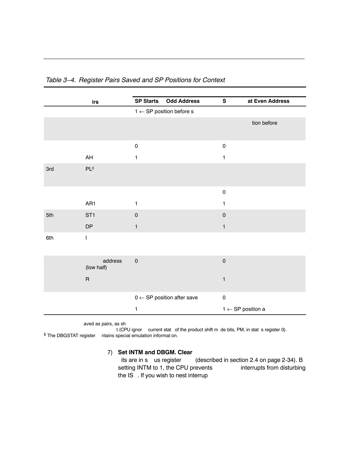
Table 3−4. Register Pairs Saved and SP Positions for Context Saves
ÁÁÁÁÁÁÁÁÁÁÁÁÁÁÁÁÁÁÁÁ
ÁÁÁÁÁÁÁÁÁÁÁÁÁÁÁÁÁÁÁÁ
Bit 0 of Storage Address
ave
Operation
†
eg
s
er
Pairs
SP Starts at Odd Address
SP Starts at Even Address
1 ← SP position before step 5
1
1st ST0 0 0 ← SP position before step 5
T 1 1
2nd
AL
0
0
ÁÁÁÁ
ÁÁÁÁ
AH
ÁÁÁÁÁÁÁÁÁ
1
ÁÁÁÁÁÁÁÁ
1
3rd PL
‡
0 0
PH 1 1
4th AR0 0 0
AR1 1 1
5th ST1 0 0
DP 1 1
6th
IER
0
0
ÁÁÁÁ
ÁÁÁÁ
DBGSTAT
§
ÁÁÁÁÁÁÁÁÁ
1
ÁÁÁÁÁÁÁÁ
1
7th Return address
(low half)
0 0
Return address
(high half)
1 1
0 ← SP position after save 0
1 1 ← SP position after save
†
All registers are saved as pairs, as shown.
‡
The P register is saved with 0 shift (CPU ignores current state of the product shift mode bits, PM, in status register 0).
§
The DBGSTAT register contains special emulation information.
7) Set INTM and DBGM. Clear LOOP, EALLOW, and IDLESTAT. All these
bits are in status register ST1 (described in section 2.4 on page 2-34). By
setting INTM to 1, the CPU prevents maskable interrupts from disturbing
the ISR. If you wish to nest interrupts, have the ISR clear the INTM bit. By
setting DBGM to 1, the CPU prevents debug events from disturbing time-
critical code in the ISR. If you do not want debug events blocked, have the
ISR clear DBGM.