Standard Operation for Maskable Interrupts
3-14
7) Fetch interrupt vector. The PC is filled with the address of the appropri-
ate interrupt vector, and the vector is fetched from that location. To
determine which vector address has been assigned to each of the inter-
rupts, see section 3.2, Interrupt Vectors, on page 3-4 or, if your device
uses a PIE module, see the System and Interrupts Reference Guide for
your specific device.
8) Increment SP by 1. The stack pointer (SP) is incremented by 1 in prepara-
tion for the automatic context save (step 9). During the automatic context
save, the CPU performs 32-bit accesses, and the CPU expects 32-bit ac-
cesses to be aligned to even addresses by the memory wrapper. Incre-
menting SP by 1 ensures that the first 32-bit access does not overwrite the
previous stack value.
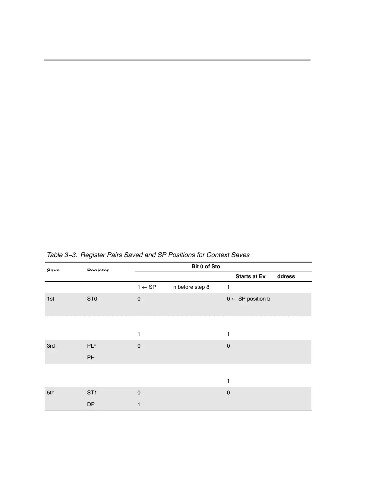
9) Perform automatic context save. A number of register values are saved
automatically to the stack. These registers are saved in pairs; each pair
is saved in a single 32-bit operation. At the end of each 32-bit save opera-
tion, the SP is incremented by 2. Table 3−3 shows the register pairs and
the order in which they are saved. The CPU expects all 32-bit saves to be
even-word aligned by the memory wrapper. As shown in the table, the SP
is not affected by this alignment.
ÁÁÁÁÁÁÁÁÁÁÁÁÁÁÁÁÁÁÁÁÁÁÁÁÁÁÁÁÁÁ
Á
ÁÁÁÁÁÁÁÁÁÁÁÁÁÁÁÁÁÁÁÁÁÁÁÁÁÁÁÁ
Á
ÁÁÁÁÁÁÁÁÁÁÁÁÁÁÁÁÁÁÁÁÁÁÁÁÁÁÁÁÁÁ
Table 3−3. Register Pairs Saved and SP Positions for Context Saves
ÁÁÁÁÁÁÁÁÁÁÁÁÁÁÁÁÁÁÁÁ
ÁÁÁÁÁÁÁÁÁÁÁÁÁÁÁÁÁÁÁÁ
Bit 0 of Storage Address
ave
Operation
†
eg
s
er
Pairs
SP Starts at Odd Address
SP Starts at Even Address
1 ← SP position before step 8
1
1st ST0 0 0 ← SP position before step 8
T 1 1
2nd
AL
0
0
AH
1
1
3rd PL
‡
0 0
PH 1 1
4th AR0 0 0
AR1 1 1
5th ST1 0 0
DP 1 1